 |
|||||||
|
|
|||||||
|
Letters Vol. 7, No. 11, pp. 34–41, Nov. 2009. https://doi.org/10.53829/ntr200911le1 Pipe Cleaning and Renovation Technologies for Effective Utilization of Existing Pipes Containing CablesAbstractThis article describes a pipe renovation technology for maintaining and repairing existing underground pipes containing telecommunications cables. This technology is urgently required because field inspections on pipes designated as suitable for accommodating multiple cables have revealed that more than half of them are defective. We are working to develop technology for repairing defective pipes without excavating them or affecting the cables within.
1. IntroductionAs optical services continue to be upgraded and expanded, there are more and more instances of optical and metal cables having to coexist in telecommunications pipes and conduits, which are feeling the strain. To enable more effective utilization of pipes, multicable laying, in which two or more cables are housed in one pipe, is proceeding rapidly. At present, multicable laying amounts to 3000 km per year on average. However, inspection results for such pipes show that 59% of them are faulty. That is, multicable installation cannot be performed in more than half of the pipes scheduled for such work. At present, pipe repairs often involve using alternative pipes and making detours, installing additional pipes, or excavating pipes that contain existing cables. A great many of the faults are caused by rusting and erosion of pipes made of metals like steel and cast-iron. The current status of pipe inspection, maintenance, and repair technologies is outlined in Table 1. Pipes are first inspected using a pipe camera with a water jet being used to expose the pipe’s inner surface. If the inspection shows minimal damage, then there is no need to excavate the pipe. However, until now, there have been no maintenance and repair technologies suitable for pipes already containing cables (occupied pipes). Consequently, when multicable laying is applied to occupied pipes diagnosed as having faults of the abovementioned types, it is always necessary to repair or replace pipes or install additional pipes, which involves excavation work, often in roads. Besides the high cost of such excavation work, the long time taken, and the difficulty of providing timely telecommunications services, road works cause traffic jams and are very noisy. All of these problems need to be alleviated.
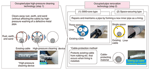
In response, we have been developing technology for maintaining and repairing defective occupied pipes without the need to excavate the pipe and without affecting the cable within [1] and we have continued to make progress (Fig. 1). In particular, after completing the development of an occupied-pipe high-pressure cleaning technology (step 1 in Fig. 1), which was previously called cable-conduit high-pressure washing technology [2], we finished development of an occupied-pipe renovation technology (previously called cable-conduit renovation technology [2]) in 2007, and that technology is the focus of the present article.
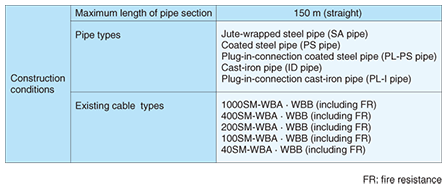
2. Occupied-pipe renovation technologyThe occupied-pipe renovation technology (step 2 in Fig. 1) repairs maintains a pipe by forming a new plastic inner pipe as a lining for a metal pipe made defective by pipe rusting or cable housing decay. The newly formed plastic pipe is designed to be mechanically strong to support weakened pipes and maintenance-free (that is, almost everlasting) to ensure that corrosion is not a concern. For this technology, we developed two elemental technologies (using different plastic pipe molding methods): a 3000-core type [2] and a space-securing type. Both technologies have the same range of applicability, which is indicated in Table 2. Currently, they are applicable only to straight sections of pipe, and the pipe’s straightness must be assessed beforehand. The internal diameter of a pipe (either empty or occupied) is checked by attempting to push in a cylindrical mandrel slightly smaller than the pipe’s inside diameter to ensure that construction work can proceed. Existing cables that are compatible with these technologies are limited to a safe range that has been verified by testing. The technical features of these two technologies are described below.
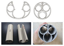
2.1 3000-core typeComponents are preformed in a factory to ensure stable quality and to enable the molding of relatively complex shapes. The liner provides three independent spaces, each able to accommodate 1000 optical fibers. In other words, even though an additional inner pipe is not used, two extra 1000-core optical cables can be installed. 2.1.1 LinerAs shown in Fig. 2, a liner (made of thermoplastic resin) provides independent spaces for housing two 1000-core optical cables in addition to an existing 1000-core optical cable (outside diameter: 31 mm). The factory-molded liner is shipped to the site in a split-open form (Fig. 2, left). On site, it is closed around the existing cable and softened by heating. The circularity of the space accommodating the existing cable (desirable considering the pipe’s heat conduction characteristics and the cable’s laying characteristics) is checked using specialized equipment.
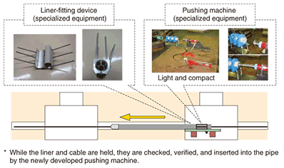
2.1.2 Construction techniquesThe onsite construction procedure is shown in Fig. 3 and summarized schematically in Fig. 4. Specialized equipment was developed for checking the liner (circularity) and pushing it into the pipe. Since this technology involves inserting a liner (which provides space for the existing cable) from a manhole, the liner is not pulled through the pipe, so the existing cable does not suffer any adverse effects from the pulling wire and pulling force. However, there are various processing steps before final verification of the installed liner in the pipe. This currently takes about 20 minutes per meter of pipe. Moreover, the connector for the liner must be airtight to prevent groundwater, earth, and sand from entering the underground pipes, which might block the pipe and prevent cable installation/removal or cause the street to cave in, so this technology is currently suitable only for straight pipes. We intend to continue developing it and will try to overcome these constraints.
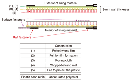
2.1.3 Acceptable characteristics of additional cablesEach of the newly created spaces can accommodate one small-diameter 1000-core optical cable (diameter: 23 mm). Problem-free cable insertion has been confirmed through cable-laying tests. 2.2 Space-securing typeLining material is pulled through the pipe and then pressed against the pipe’s inside wall and cured to form a solid lining. Processing up to impregnation of thermosetting resin into the lining is carried out in a factory, and then curing and molding are performed on site. To allow the lining material (which is flexible before being cured) to be pulled through the pipe, it is designed to slide easily in straight pipes. Once this renovation work has been finished, it is possible to install one additional inner pipe in the renovated telecommunications pipe. This technology was designed to suit a 36-mm-external-diameter inner pipe (IP30), which can accommodate one 1000-core optical cable. Since the lining material is pulled into the conduit, in this case, measures are taken to protect the existing cable from any adverse effects of the pulling force. 2.2.1 Lining materialTo ensure that the final liner is strong enough to be self-supporting, because it is applied to weakened pipes, it is made of fiber-reinforced plastic (FRP), which is an unsaturated polyester (thermosetting resin) reinforced with glass fiber. The liner’s configuration shown in Fig. 5. The inner and outer sides have the same material composition. In a factory, plastic-retention felt is impregnated with liquid unsaturated polyester resin, and the lining material is shipped to the construction site in an uncured condition. Since curing progresses gradually at room temperature, it is transported in special cold-storage containers. To achieve a good balance between strength and cost, the glass fiber consists of a standard chopped-strand mat mixed with stronger roving-cloth fibers. The outer surface of the lining material is covered with a polyethylene film to prevent resin seepage before curing. After the installation work, the lining material has the form of a solid plastic pipe-like liner with a wall thickness of 3 mm.
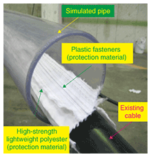
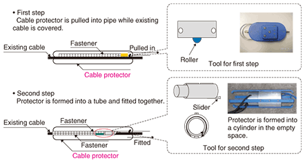
2.2.2 Construction techniques(1) Cable-protection and lining material pulling processes First, to protect the existing cable from rubbing when the lining material is pulled through the pipe, cable protection material is pulling in at the same time. It is composed of high-strength lightweight polyester and plastic fasteners (Fig. 6) and formed into a protector in a two-step process (Fig. 7). First, the step-1 tool is pulled into the pipe while it surrounds the existing cable in the pipe. Next, the step-2 tool (cylindrical to fit the pipe) is drawn into the pipe, and the protector is fitted together and closed around the cable. Since the weight of the cable alone effectively acts only over the length of the tool, pulling under low tension is possible.
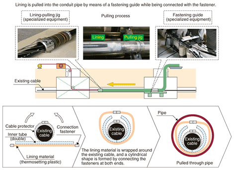
Next, the ends of the lining material (connected to a pulling wire) are hoisted up at one end, and the lining material is pulled into the conduit from the other end (Fig. 8). Specialized equipment is used: a lining-pulling jig ensures connection between the pulling wire and the lining material and a fastening guide fits the fastener to the inside of the lining material while gripping the cable. Furthermore, a double inner tube (for the curing and molding processes) is simultaneously pulled into the pipe. The lining pulling speed is standardized as 3 m/min., so the time required for the pulling process to cover a distance of 150 m is about one hour.
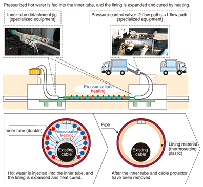
(2) Curing and molding The curing and molding processes are illustrated in Fig. 9. Pressurized hot water is passed through the inner tube (see Fig. 8) inserted between the existing cable and the lining material. This pressure causes the lining material (and the inner tube) to expand until it presses against the inner wall of the pipe. The hot water then cures the thermosetting resin in the lining material and molds it to the pipe’s inner wall. To ensure that the lining forms smoothly on the inner wall, the inner tube has a double-wall structure. Specialized equipment—an inner-tube pressure-control valve and an inner-tube detachment jig—is used for these processes. To avoid adverse effects on the existing cable, the construction specification limits the water temperature to 65°C and water pressure to 0.1 MPa. The curing and molding processes take about three hours.
2.2.3 Multicable laying after renovationThe finished structure has an inner diameter of 66 mm. The maximum pulling force that can be used for laying the additional inner pipe (IP30) has been confirmed in tests to be the same as the maximum permissible tensile force during multicable laying (980 N). 3. Future plansThe occupied-pipe renovation technology (step 2) is scheduled to be introduced commercially after a trial-run of the construction techniques. Furthermore, development is already underway for the next step (step 3) with the aim of expanding the application field to include curved pipe segments and improving efficiency by, for example, speeding up construction work and reducing costs. References
|
|||||||


