 |
|||||||||||||||||||||||||||||||
|
|
|||||||||||||||||||||||||||||||
|
Letters Vol. 7, No. 11, pp. 42–47, Nov. 2009. https://doi.org/10.53829/ntr200911le2 Technologies for Checking Outside Optical Distribution EquipmentAbstractThis article describes technologies for checking outside optical distribution equipment, which is being deployed in increasing quantities along with the expansion and diversification of optical services. These technologies are designed to reduce costs and improve checking performance.
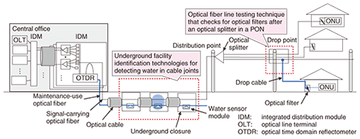
1. IntroductionThe number of fiber-to-the-home (FTTH) subscribers in Japan is increasing rapidly and exceeded 15 million in March 2009 [1]. The structure of the optical access network used to provide NTT’s FTTH-based Internet protocol (IP) connection services, called FLET’s Hikari, is shown schematically in Fig. 1. This optical equipment must operate efficiently in order to ensure good service quality. For this purpose, we are developing a water sensor module for detecting water penetration in underground closures. These modules enable the maintenance system to identify two or more water-penetrated underground closures along one fiber. We are also developing a technique for checking for optical filters installed in front of optical network units (ONUs) in optical fiber branches after an optical splitter in a passive optical network (PON) to distinguish between live (signal-carrying) and unused (non-signal-carrying or dark) fibers.
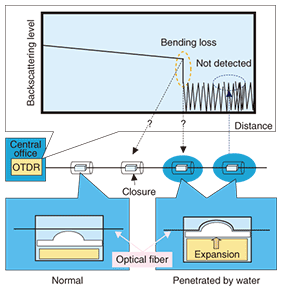
2. Underground facility identification technologies for detecting water in cable joints2.1 Water penetration detection technology and a related problemJoins between lengths of optical fiber are made at closures. If water penetrates an underground closure over time, it can cause an increase in optical loss and degrade the fiber’s mechanical strength. For this reason, each underground closure contains a water sensor module attached to the same maintenance-use optical fiber. The water sensor module and the detection mechanism are shown in Fig. 2. If water penetrates an underground closure, an absorbent material in the sensor module expands and applies a bending force to the maintenance fiber. As the absorbent material, polyacrylic acid was chosen because its performance and long-term reliability have been determined. The bending force induces bending loss, which can be detected in the power level of the backscattered signal with an optical time domain reflectometer (OTDR). Moreover, the OTDR can determine the distance at which the bending loss occurs, so it is possible to identify which closure has a problem. Therefore, water penetration in all underground closures can be monitored by performing periodic tests with an optical fiber line testing system [2].
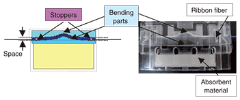
Currently, we use a test light with a wavelength of 1650 nm for the periodic test. However, the bending loss should not exceed the dynamic range of the OTDR when water has penetrated underground closures, and it is impossible to detect water in the underground closures at long distances. Moreover, it is difficult to identify a specific underground closure where water has penetrated using the OTDR if adjacent underground closures are too close together. This has a considerable influence on the promptness of repair work. 2.2 Optical loss control using new water sensor moduleOur design for the new water sensor module is shown in Fig. 3. When water penetrates an underground closure containing a conventional water sensor module [2], the bending part of the module applies lateral force to the optical fiber as well as bending force. It is not easy to control the insertion loss caused by both these forces. In the new water sensor module, the region containing the bending parts incorporates stoppers, as shown Fig. 3, which can reduce the insertion loss caused by the lateral force. In addition, the bending radius of the bending part is smaller. By taking these measures, we were able to optimize the bending loss that occurs during water penetration.
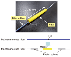
2.3 Marker for maintenance-use fiberWe examined the possibility of marking the maintenance-use fiber to facilitate the identification of water-penetrated underground closures during maintenance work. We chose to use the reflection method to identify the marker because we can use the conventional OTDR usually used for maintenance work including the periodic test and because the insertion loss caused by the marker has no influence on the OTDR’s dynamic range. The marker that we have developed is shown in Fig. 4. It is almost the same size as a fiber protection sleeve so that it can be stored in the fiber storage tray of an underground closure. It has a fiber ribbon at each end and is inserted into the maintenance-use fiber by fusion splicing. It incorporates an optical fiber with a fiber Bragg grating (FBG) inscribed into it, and higher reflectivity than the popular MT connector is achieved by controlling the return loss. As a result, we were able to produce a way of marking the maintenance-use optical fiber.
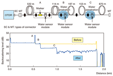
2.4 Application of new water sensor module and markerWe evaluated the new water sensor module and marker before and after water penetration. The experimental setup and the measured OTDR traces are shown in Fig. 5. The total length of the optical fiber was 1866 m. Prototype water sensor modules were attached to the maintenance-use fiber in closures at three points, which were 532 m (Point A), 646 m (Point B), and 996 m (Point C) from the OTDR. The prototype marker was spliced in at point A because points A and B were close to each other. The wavelength of the test light was 1650 nm and the pulse width was 100 ns. From the OTDR traces in Fig. 5, we were able to detect both the water penetration locations (points B and C). Moreover, it was easy to determine that the cable joint at point B had been penetrated by water from the reflection from the marker at point A.
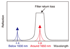
3. Optical fiber line testing technique that checks for optical filters after an optical splitter in a PON3.1 ProblemIn recent years, the demand for broadband access services has increased throughout the world. FTTH is the most promising approach for providing these services because of its large capacity and cost effectiveness. These services are mainly provided using PON topologies, such as broadband, Gigabit capable, and Gigabit Ethernet (B-PON, G-PON, and GE-PON) [3]–[5]. Many optical fiber cables are being installed every day to meet the current demand. During the installation and maintenance of optical fiber communications networks, field engineers must first correctly identify a specific fiber from a bundle of fibers to avoid the incorrect cutting and/or connection of an optical fiber at a worksite. In particular, they must avoid cutting live fibers in order to maintain service reliability. Therefore, it is necessary to distinguish between live and unused fibers in fiber branches. An optical fiber identifier [6]–[8] that uses a non-destructive macrobending technique [9]–[10] is widely used as a convenient tool for identifying a specific fiber used for maintenance purposes. However it is difficult to identify an optical fiber in PONs that have optical splitters. This is because the optical power of the test light launched from a central office is distributed equally among the fiber branches by an optical splitter, so a conventional optical fiber identifier cannot identify a specific fiber. Nevertheless, field engineers need to be able to select unused fibers during cable installation or removal work. In this section, we describe a new technique for construction work performed to install optical lines for PON-based services and describe a novel measuring technique that checks for optical filters located in front of an ONU in fiber branches for PONs with optical splitters. The purpose is to determine whether an optical fiber is in use or not. 3.2 Optical fiber line testing system and optical filter characteristicsAs a model of the PON access network with an optical fiber line testing system, we used the configuration shown in Fig. 1. Optical fiber line testing systems are installed to reduce construction and maintenance costs and to improve service reliability in PON systems [11]. They essentially consist of optical couplers, which introduce a test light into fiber lines in a central office, and optical filters, which are installed in front of an ONU and allow the communication light from an optical line terminal (OLT) to pass but cut off the test light. The optical filter is an FBG filter, which has wavelength-dependent characteristics for inline monitoring [12]–[13]. The center wavelength of the test light is 1650 ± 5 nm in accordance with ITU-T Recommendation L.41 [14]. The return loss spectrum of light reflected by the FBG filter is shown in Fig. 6. A test light with a wavelength of 1650 ± 5 nm is reflected strongly, but test lights at other wavelengths (e.g., 1630 nm and below) are hardly reflected at all. The wavelength dependency of test lights at these two wavelengths reflected by the filter can be utilized to determine whether or not a filter is present. Since a live fiber must have an optical filter to enable inline monitoring with an optical fiber line testing system, field engineers working on branches after an optical splitter can distinguish between live and unused fibers by knowing whether or not there is an optical filter at the end of the branch.
3.3 Basic concept of the methodOur method recognizes the presence of an optical filter by detecting test lights reflected from filters in the branch after an optical splitter. Its configuration is shown in Fig. 7. This method involves generating test light and monitoring it using the non-destructive macrobending method used for an optical fiber identifier [8]–[9]. The light source module produces two wavelengths, namely primary wavelength (λp) and secondary wavelength (λs). The monitoring equipment consists of two photodetectors (PD1 and PD2) and a bender that lets us monitor the leaked optical power caused by macrobending. PD1 mainly detects test lights reflected at the far end of the fiber line while PD2 mainly detects test lights transmitted directly from the test light source. PD1 detects the optical powers at two wavelengths (λp and λs). By comparing the difference in the power levels at these two wavelengths, we can determine whether or not there is a filter at the end of the fiber line.
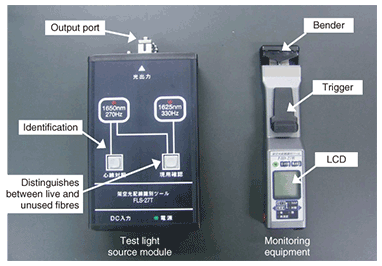
3.4 Optical filter checking toolThe prototype of our optical filter checking tool is shown in Fig. 8. The light source module generates light at 1650 and 1625 nm and operates on AC power or batteries. The test lights are modulated at 270 and 330 Hz, respectively. The receiver has a bender and detects the power of the induced leaked test light. We designed the receiver to be light and compact for use in aerial optical closures. It runs on batteries because it is designed for outdoor use. Field engineers can use this tool to identify unused fibers during cable installation or removal work.
4. ConclusionWe described a water sensor module that can detect water penetration in underground closures and enables the maintenance system to detect two or more penetrated closures along one fiber and a technique for checking for optical filters in optical fiber branches in PONs with optical splitters. These methods will help to achieve smooth and correct construction and maintenance work for optical fiber cables in access networks. References
|
|||||||||||||||||||||||||||||||


