|
|||||||||||||||||
|
|
|||||||||||||||||
       |
Special Feature: Trends and Business Prospects for Human-area Networking Technology––Connecting People, Objects, and Networks Vol. 8, No. 3, pp. 19–24, Mar. 2010. https://doi.org/10.53829/ntr201003sf4 Firmware Technology for Human-body Near-field CommunicationAbstractWe describe firmware technology for services, such as entry gate management and business card exchange, based on modules with a bidirectional communication function. In particular, target services, required functions, and the firmware structure are described. 
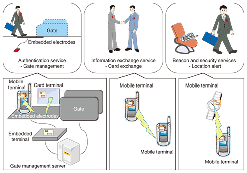
1. IntroductionRedTacton is a new communication technology that can be used to easily exchange information through natural actions such as touching. It provides communication between the mobile terminals of two users or between a user’s mobile terminal and an embedded type of terminal in the environment (in doors, floors, objects, etc.) by using the electric field on the surface of the human body. It has been applied to authentication services (e.g., entry gate management), information exchange services (e.g., business card exchange), and beacon and security services (e.g., functions that enable a cell phone to alert the user to its presence or that lock it to prevent unauthorized use by other people). Since users do not need to take any special action (e.g., taking out, operating, or holding up a device to use it) and they automatically know whether the device is present or not, RedTacton could be more useful than other communication methods such as wireless-, infrared-, or Bluetooth-based ones. To achieve this convenience, it is necessary to efficiently control the RedTacton module (an advanced, compact electric-field communication module providing bidirectional communication [1]) with low power consumption. Moreover, to achieve stable service, it is necessary to raise the communication quality of electric-field communication. This article describes the functions required for the firmware and the service structure. 2. Communication terminals with RedTacton moduleIn the services shown in Fig. 1 as examples, there are various communication devices, such as mobile devices and stationary devices. When a RedTacton module is implemented inside a device and operated, the actions of the firmware in each device may differ in accordance with the environment in which the module is operating. For example, the power supply may be a battery or the mains AC supply and the module may or may not be controlled by a supervising device.
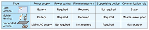
There are three kinds of communication devices (card, mobile, and embedded terminals) that can have a RedTacton module (Table 1).
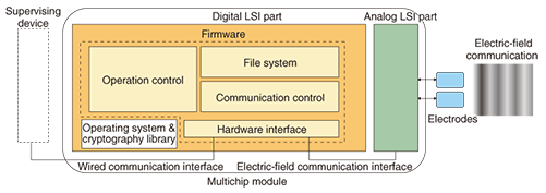
(1) Card terminal: a thin device in card form. Since power is supplied by a compact battery, the need for low power consumption is especially important. To ensure that the card terminal can provide the same services as existing IC (integrated circuit) cards, it must have a file management function for managing data for authentication or certification. As the card terminal works without a supervising device, it is a slave in the master-slave communication model (in which slaves are under a master’s control). (2) Mobile terminal: a component built into a mobile device, such as a cell phone. It obtains power from the built-in battery of that device. Since it is used for the same services as IC cards or for services using communication between mobile terminals, a mobile terminal must have a file management function and a function for connecting to a supervising device. A mobile terminal works under a supervisor and has a file system. It has three roles: either a master or slave in master-slave communication or a peer in peer-to-peer communication (in which control between the terminals is on an equal basis). As a slave, it communicates with other embedded terminals or mobile terminals (acting as masters) and as a master it communicates with other mobile terminals (acting as slaves). (3) Embedded terminal: a device built into a door or gate. Since it is powered by mains AC, low power consumption is not an important issue. Although an embedded terminal does not need to have a file management function in order for the gate management server to keep user data, it needs to have a function for connecting to a supervisor (e.g., the gate management server). Since an embedded terminal works with a supervisor, it is the master in master-slave communication or a peer in peer-to-peer communication. By combining these three types of terminals, we can create authentication, information exchange, and beacon & security services. 3. Firmware requirementsFor the firmware to be implemented on all three types of terminal, it must meet the following requirements. (1) For every terminal: The firmware must be loaded onto a module in every terminal and must be able to adapt to different terminal types easily. (2) User data access control: The firmware must store the user data managed by the file management function and control access to that data. (3) Authentication and cryptography: The firmware must authenticate devices before the user data managed by the file management function is accessed and must encrypt the data for transmission. (4) Rollback function: The firmware must have a rollback function that returns the service in progress to the initial state if the process is interrupted by the power supply being shut off. (5) RedTacton module detection: To handle cases where there are two or more RedTacton modules within communication range, the firmware must have an anticollision function for detecting all the modules and choosing one to communicate with. (6) Beacon function: When a mobile terminal sends short data bursts periodically, e.g., in a cell phone location alerting service, it will be active for a long time. The firmware must have a beacon function that periodically sends data to other RedTacton modules without initiating a session (communication path) in order to limit the power consumption. (7) Power supply control function: The firmware in card and mobile terminals must have a function for transitioning from an active state to a sleep state when idle and it must supervise the power supply voltage in order to reduce battery consumption and trigger an alert when the power supply voltage drops. (8) Update function: The firmware must be able to update itself through the network by remote control if it is in a networked mobile terminal, such as a cell phone. 4. Firmware structureThe structure of firmware that meets the above requirements is shown in Fig. 2. Here, the multichip module is another name for a RedTacton module from the hardware viewpoint. Firmware is located in the digital LSI (large-scale integrated circuit) part of the RedTacton module and has an electric-field communication interface and a wired-communication interface. The electric-field communication interface is the gateway to another RedTacton module through the analog LSI part (hardware for achieving electric-field communication) of the RedTacton module. The wired-communication interface is the gateway to a supervising device.
5. Structural componentsThe firmware uses the following structural components.
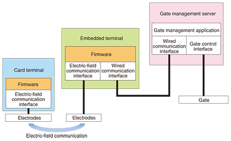
6. Service operation caseHere, we introduce an authentication service (gate management) as an example of a service in operation. This service concept is shown on the left side of Fig. 1. First, a user with a card terminal steps on the embedded electrodes beneath the gate. The authentication process then begins through electric-field communication between the card terminal and the embedded terminal. If the user is successfully authenticated, the gate opens. The system structure of the firmware for achieving this service is shown in Fig. 3. An application in the gate management server (hereinafter, server) that controls the opening and closing of the gate also controls data transfers through electric-field communication between card terminals and the embedded terminal by sending a command to the firmware of the embedded terminal.
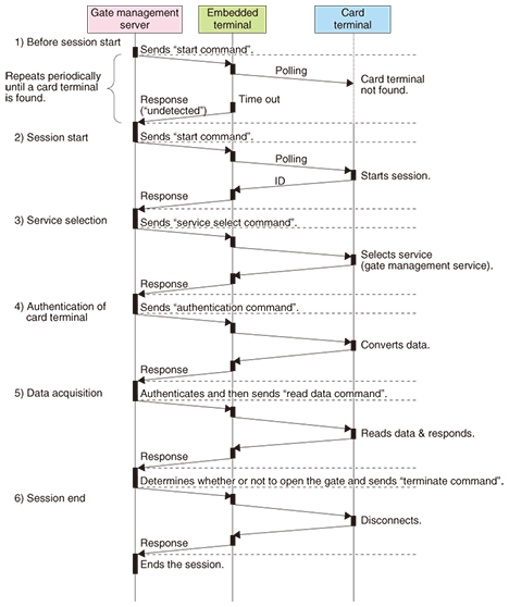
The process sequence of this service is shown in Fig. 4.
(1) Before session start The server periodically sends a “start command” for the embedded terminal to detect card terminals. The embedded terminal performs polling for card terminals accordingly. If there are no card terminals within communication range or if the embedded terminal does not receive any responses from card terminals that are within range, the embedded terminal returns “undetected” to the server. (2) Session start If there are card terminals in range and the embedded terminal receives responses from them, the embedded terminal chooses one to communicate with by using its anticollision function if necessary and returns the ID of the detected card terminal to the server. After that, a session is set up between the embedded terminal and the card terminal, and communication is initiated. (3) Service selection In this example, the server decides that gate management is the service required and sends a “service select command” to the card terminal via the embedded terminal. When the card terminal receives the service select command, it selects the gate management service application from among its applications. (4) Authentication of card terminal The server sends an “authentication command” containing authentication data for the authentication process, such as a random number, to the card terminal via the embedded terminal so that the server can verify that the card terminal is a legitimate communication partner. When this command is received, the card terminal converts the data for authentication and returns the resulting converted data. In response, the server authenticates the data and determines that the card terminal is legitimate. (5) Data acquisition The server sends a “read data command” to the card terminal via the embedded terminal in order to read the card terminal’s expiry date, cardholder information, etc. When this command is received, the card terminal reads the related data in the file system and sends the requested data. From the contents of this response, the server determines whether or not to open the gate and operates the gate in accordance with the decision. (6) Session end The server sends a “terminate command” to the card terminal via the embedded terminal. When this command is received, the card terminal responds with an acknowledgment and disconnects the session. When it receives the response, the server ends the session. If no response is received, the server automatically ends the session after a preset time. 7. Future directionWe plan to evaluate the firmware by applying it to target services expected to turn into future business. In addition, we will develop and adjust its performance on the basis of the evaluation results and improve its ease of use. References
|
||||||||||||||||