 |
|||||||||||||||||||||||||||||||||||||||
|
|
|||||||||||||||||||||||||||||||||||||||
|
Regular Papers Vol. 8, No. 7, pp. 30–39, July 2010. https://doi.org/10.53829/ntr201007rp1 Frequency Domain Equalization Design for Coherent Optical Single Carrier TransmissionAbstractIn this paper, we present two coherent optical single carrier transmission (COSC) configurations with frequency domain equalization (FDE) for decoding the received signal with low calculation complexity. The FDE configuration, which uses a unique word (UW) as a cyclic prefix, compensates for phase noise by using the received signals corresponding to the UW. The overlap FDE (OFDE) configuration uses OFDE for chromatic dispersion compensation and uses time domain equalization for residual inter symbol interference compensation. Transmission performances for a 25-Gbit/s non-return-to-zero quadrature phase-shift keying (QPSK) single-polarization signal over single-mode fiber in the FDE and OFDE configurations are demonstrated. Since the insertion of a large UW degrades the transmission efficiency, the FDE configuration is effective in short-distance transmission. In long-haul transmission, OFDE achieved high transmission performance: in experiments, 25-Gbit/s COSC achieved a high Q factor of 11.6 dB for a transmission distance of 4320 km.
1. IntroductionThe next-generation optical communication systems must offer much higher data transmission rates, e.g., up to 100 Gbit/s per channel. At these rates, the transmission performance of optical fiber systems is severely degraded by the effects of chromatic dispersion (CD) and polarization mode dispersion (PMD). CD expresses the phenomenon that the propagation speed of a signal in an optical fiber depends on the optical frequency, and PMD is caused by the time delay occurring between two orthogonal polarization components during propagation in an optical fiber. Various digital signal processing (DSP) techniques such as orthogonal frequency division multiplexing (OFDM) [1]–[4] and coherent optical single carrier transmission (COSC) with time domain equalization (TDE) [5]–[7] have been proposed to compensate for the effects of CD and PMD without optical dispersion compensation. We recently proposed COSC with frequency domain equalization (FDE) [8], [9], which is used in the next-generation wireless cellular system, i.e., 3G Long Term Evolution (LTE) [10]. COSC with FDE (COSC-FDE) improves the transmission quality by reducing the calculation complexity owing to its block-to-block operation by adding a cyclic prefix (CP) for each block. FDE is very attractive because it has much lower calculation complexity than TDE when the number of taps for the equalizer is large [11]. Although OFDM also has low calculation complexity because of its block-wise operation, COSC-FDE has the advantages that the peak-to-average-power ratio of COSC signals is much smaller than that of OFDM signals and it is more robust against fiber nonlinearity. This paper describes two COSC-FDE configurations. One is the FDE configuration, which uses a unique word (UW) as a CP to eliminate inter block interference (IBI). Our FDE configuration compensates for the phase noise by using the received signal corresponding to the UW [12]. The FDE weight is calculated from the pilot symbols by applying the minimum mean square error (MMSE) criterion. This configuration is robust against the phase noise; the overhead of UW degrades the throughput in long-haul communication systems due to the large CD effect. To overcome these problems in the FDE configuration, the overlap FDE (OFDE) configuration has been proposed. This uses OFDE [13], [14] and TDE for CD compensation and residual inter symbol interference compensation, respectively. As a practical system, OFDE was proposed for wireless systems to improve the transmission efficiency of FDE by dispensing with the CP [15]. Although FDE with a large block size is vulnerable to phase noise and synchronization errors, the OFDE configuration can compensate for the remaining inter symbol interference by using TDE. Thus, this OFDE configuration is attractive, especially for very-high-data rate optical communications in long-haul optical systems. This paper also describes the transmission performance of 25-Gbit/s non-return-to-zero (NRZ) quadrature phase-shift keying (QPSK) single-polarization signals over ITU-T G.652 single-mode fiber (SMF) without optical dispersion compensation (ITU: International Telecommunication Union, Telecommunication Standardization Sector). The effectiveness of the FDE configuration was confirmed by an experiment using 240 km of SMF. Furthermore, the Q factor of 25-Gbit/s COSC transmission with the OFDE configuration was measured for long-haul transmission and we found that the OFDE configuration attained a Q factor of 11.6 dB for 4320 km of SMF using 128 overlapped samples (512-point fast Fourier transform (FFT)) for CD compensation. This paper is organized as follows. Section 2 describes COSC transmission based on the FDE and OFDE configurations. Section 3 describes the COSC transmission experimental setup. Section 4 presents the measurement results including optical signal-to-noise ratio (OSNR) performance and Q-factor values. Finally, Section 5 summarizes the paper. 2. COSC design2.1 FDE configurationDSP block diagrams of the transmitter and receiver for COSC-FDE transmission are illustrated in Fig. 1. At the transmitter, the binary information sequence is first mapped to PSK or quadrature amplitude modulation symbols (Fig. 1(a)). The UW is inserted into each symbol block as a CP, which is similar to the CP in OFDM. The UW is an effective way of virtually eliminating the IBI caused by the effects of CD and PMD in COSC transmission. A pilot symbol sequence is then added at the beginning of the transmission data frame. The modulated symbol sequence is fed to an optical modulator. The transmitted signals are received via optical fiber. At the receiver, the received signals corresponding to two polarization components are obtained using a polarization-diversity optical 90° hybrid (Fig. 1(b)). The received signals are demodulated by FDE. Then phase noise compensation is applied using the received unique word (UW).
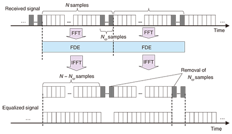
The FDE configuration is schematically illustrated in Fig. 2. A UW of Ncp samples is inserted at the end of each FFT block (N samples). Since each UW is a known symbol sequence, it can be used for synchronization and equalization. After FDE and inverse FFT (IFFT) operations, the UW is removed. The ratio of the UW overhead to the FFT block is given by Ncp/N. Thus, the transmission efficiency degrades as the required UW length increases.
If the UW is longer than the dispersion size of channel impulse responses determined by the effects of CD and PMD, the received signal vectors rX(tn) and rY(tn) are given by  where N is the FFT size, A is the oversampling factor, Ts is the duration of a single symbol, and rX(tn) and rY(tn) are the received signals in the X and Y polarization channels, respectively. Superscript T denotes a transposition. The receive timing tn is defined as where n is the discrete time corresponding to the baud rate and Ts is the duration of a single symbol. The received signal vectors in single polarization transmission are expressed using the transmission signal vector sn as  where HX and HY are N × N circulant channel matrices of whose first row vectors hX and hY are expressed as [hX,0, ..., hX,L–1, 0, ..., 0] and [hY,0, ..., hY,L–1, 0, ..., 0], where hX,l and hY,l denote the l-th complex-valued channel gain of the X- and Y-polarization inputs, respectively. The transmission signal vector sn and noise vectors nX and nY are given by  where nX,i and nY,i have a zero-mean complex Gaussian process with variance of σ2. Since HX and HY are circulant matrices, they are expressed as  where  GX,k and GY,k represent the channel gain at the k-th frequency and are given by GX,k=  Joint 1-tap equalization and polarization diversity combining are then carried out in the frequency-domain as where ,WF,X and WF,Y of size N × N are equalization weight matrices. Now let us consider the MMSE weight. According to [16], the receive weight is given by 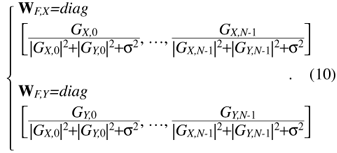 The FDE weight based on the MMSE criterion is computed using the pilot symbol period. The estimated signal un is obtained by IFFT as Phase noise compensation is carried out by using the estimated signal corresponding to the UW. The phase noise θ is estimated as θ = arg{ Both the COSC-FDE and OFDM systems perform block-wise equalization in the frequency domain. The difference between OFDM and COSC-FDE is as follows. In OFDM transmission, IFFT and FFT are used at the transmitter and receiver, respectively. On the other hand, in COSC-FDE, they are both used at the receiver. Since DSP-based IFFT is not required at the transmitter, COSC-FDE does not need to use a digital-to-analog converter, so the complexity at the transmitter is less than in the OFDM system. 2.2 OFDE configurationA block diagram of the DSP for the OFDE configuration is shown in Fig. 3. At the transmitter, binary information is first modulated. Then, pilot symbols are inserted at the beginning of the data sequence and the signal is transmitted. At the receiver, the received signals corresponding to two polarization components are obtained. The received signal is demodulated by OFDE and TDE. First, CD compensation is performed using OFDE. After the effect of CD has been removed, TDE is performed. After timing and frequency synchronization, TDE calculates the reception weight based on a constant modulus algorithm by using the data signal and a blind algorithm. The tap size of TDE is much smaller than that of OFDE because the temporal dispersion of the received signal is significantly reduced by the CD compensation. After the second equalization, carrier recovery is conducted using the carrier phase estimation method [17].
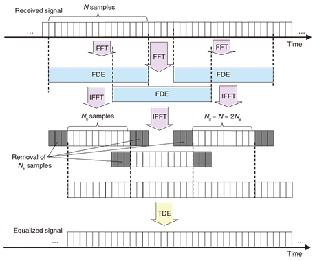
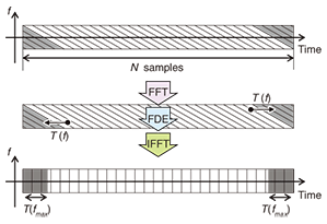
2.2.1 CD compensationA schematic diagram of OFDE is shown in Fig. 4. In the OFDE configuration, the number of FDE operations increases in proportion to the number of overlapping samples Ne. However, the transmission efficiency is better than with the FDE configuration since no CP is required in this configuration. In the OFDE configuration, first, FFT is performed on the N samples of the received signal. The FDE block then multiplies the received signal in the frequency domain by a fixed weight calculated using the equation in [18]. The frequency domain transfer function weight is given as where c is the speed of light, L is the transmission distance, D is the dispersion coefficient of the optical fiber, f is the frequency at the baseband signal, and fc is the center frequency of the optical signal. Since fc >> f, (fc − f)2 can be approximated as fc2. Note that f is the frequency not of the optical signal but of the electrical signal and −Fs/2 ≤ f ≤ Fs/2, where Fs is the sampling frequency at the analog-to-digital converter. Here, the dispersion slope is ignored since its effect is much smaller than that of CD. Since the CD is caused by group velocity dispersion in the optical fiber, the transfer function shifts the received signal in time. This shift T(f) is given by It causes a large dispersion of transmitted symbols in long-haul transmission. After N-point IFFT, the first Ne samples and the last Ne samples in the N samples are removed, as shown in Fig. 4, and the remaining N0 (= N – 2Ne) samples, which demonstrate zero IBI, are extracted. Therefore, the compensated signal is continuously obtained since FDE is performed in an overlapped FFT block shifted by N0 samples (< N).
The concept of FDE for CD compensation in the case where D > 0 is shown in Fig. 5. Here, the parallelograms and rectangles denote transmitted symbols. In this figure, the samples that were affected by CD are drawn as parallelograms because the group velocity of the optical signal increases as the frequency falls when D > 0. The gray samples correspond to the other FFT block samples and cause IBI. When FDE is used, the parallelogram samples are compensated for and become samples (rectangles) whose dispersion is much less than those of the parallelograms samples. However, the samples at the edge of the block contain the samples corresponding to other blocks. Therefore, Ne samples must be removed to suppress the IBI.
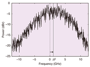
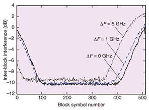
The required number of overlapped samples Ne is given by where fmax is the frequency of the spectrum edge of the received signal. When the transmission signal occupies Ft Hz, fmax is expressed as Ft/2. If Ne does not satisfy the condition in Eq. 14, IBI degrades the transmission performance. If there is a frequency offset ΔF between the transmitter and receiver, fmax is greater than Ft/2. This is because the distribution of the received baseband signal in the frequency domain shifts owing to the frequency offset. The electrical spectrum of the received signal of 25-Gbit/s QPSK (12.5 Gbaud) using a 25-Gsymbol/s analog-to-digital converter with a frequency offset of 1 GHz is shown in Fig. 6. Thus, fmax is expressed as Ft/2 + ΔF. Thus, Ne must be set large enough to avoid the IBI increase caused by the frequency offset that might be generated in the transmission systems, or the frequency offset must be compensated for before CD compensation. IBI distributions in the N samples after IFFT are shown in Fig. 7. The symbols were transmitted through 4000 km of SMF and the effect of CD was compensated for by FDE with 512-point FFT (Nc =512). Figure 7 shows the distributions without a frequency offset and with frequency offsets of 1 and 5 GHz. The distributions shifted as the frequency offset increased, but was symmetrical without an offset.
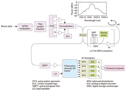
2.2.2 TDE for phase noise compensationTDE calculates the equalizer coefficients using the received signal. To show the derivation of the equalizer coefficients, we define the received signal vectors ¯rX(tn) and ¯rY(tn) as  where M is the tap size of TDE and M << N. Thus, the vector sizes of ¯rX(tn) and ¯rY(tn) are much smaller than those of rX(tn) and rY(tn). In the TDE block, the equalizer coefficients are calculated as where α is the step size parameter. The estimated transmission signal un is expressed as  TDE can update the equalizer coefficients using the data symbols of QPSK or binary PSK. 3. Experimental setupThe experimental setup is shown in Fig. 8. At the transmitter, the continuous-wave optical carrier from an external cavity laser was modulated by an optical IQ-modulator (I: in-phase, Q: quadrature). We used a signal wavelength of 1552.12 nm on the ITU grid. A pulse pattern generator was used to generate continuous binary IQ baseband signals to which CP and pilot symbols were applied, and no optical dispersion compensation fiber was used. The transmission line consisted of two spans of 80-km ITU-T G.652 SMF and erbium doped fiber amplifiers. The average dispersion was 17 ps/nm/km. For bit error rate (BER) performance evaluation of the FDE configuration, the transmission line consisted of three spans of 80-km ITU-T G.652 SMF; the transmission distance was 240 km and the total dispersion of the transmission line was 4080 ps/nm. For Q-factor evaluation of the OFDE configuration, the transmission distance of the SMF was set to 800–4320 km, so the corresponding accumulated CD vales were 13,600–73,400 ps/nm. We used distributed Raman amplification to improve the received OSNR. The on/off Raman gain was 7 dB. The input power to each span ranged from -4 to 0 dBm. At the receiver, the transmitted NRZ-QPSK signal was combined with the signal from a local oscillator in a polarization-diversity optical 90° hybrid. The I and Q parts of the two polarization components were fed to four balanced photodetectors. The local oscillator was an external cavity laser with 100-kHz linewidth tuned to the transmitted signal wavelength. The balanced photodetector outputs were sampled and digitized using a digital storage oscilloscope. The sampling rate was 25 Gsample/s. In the offline process, a DSP implementation of two-stage equalization was performed. The BER was then estimated from the data sequence of 1.9 million bits. The bit rate before coding was 25 Gbit/s. Taking into account an additional 7% for forward error correction coding and 0.6% for pilot symbols, the transmission data rate was 23.11 Gbit/s.
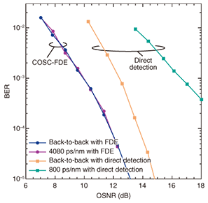
4. Experimental resultsThe BER performance of COSC in the FDE configuration is illustrated in Fig. 9 as a function of OSNR for the back-to-back and post-transmission conditions. The number of samples for the UW and the block size for FFT were set to 32 and 256, respectively ((Ncp, N) = (32, 256)). The corresponding UW and FFT block lengths were 1.28 and 10.24 ns, respectively. For comparison, we also plotted the BER performances with direct detection of 25-Gbit/s differential QPSK (DQPSK) for back-to-back and 800-ps/nm transmission. The BER performance with FDE was about 2 dB better than that with direct-detection DQPSK in the back-to-back case since COSC-FDE uses coherent detection. Furthermore, the performance of COSC-FDE after 240-km-SMF (CD = 4080-ps/nm) transmission was not degraded, while that of direct-detection DQPSK was significantly degraded, even in 800-ps/nm transmission.
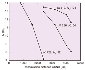
The Q factor of COSC in the OFDE configuration as a function of transmission distance is shown in Fig. 10. The numbers of FFT points and overlapped samples in OFDE, (N, Ne) were set to (512, 128), (256, 64), and (128, 32), and TDE with 16 taps (M = 16) was used as the second equalizer. Equation 14 shows that when fmax is set to 6.25 GHz, which is half the baud rate of NRZ-QPSK, the required Ne values in OFDE are 42 and 84 for transmission distances of 2000 and 4000 km, respectively. Figure 10 shows that N = 512 yielded higher Q factors than N = 128 or 256 for 2000- and 4000-km SMF. This performance degradation with (N, Ne) = (128, 32) and (256, 64) was caused by the IBI in OFDE since Ne did not satisfy the condition of Eq. 14. When fmax is 6.25 GHz, Eq. 14 also shows that OFDE configurations with (N, Ne) = (512, 128), (256, 64), and (128, 32) compensate for the CD of 6095, 3048, and 1524 km of SMF, respectively. However, the Q factor with (N, Ne)= (256, 64) for 2400 km and the Q factor with (N, Ne) = (128, 32) for 800 km are smaller than those with (N, Ne) = (512, 128). This is because the spectrum of the received signal occupies more than 12.5 GHz as a result of the frequency offset, as shown in Fig. 6. The Q factor of COSC with (N, Ne) = (512, 128) gradually decreased as the transmission distance increased; however, Ne = 128 is large enough for a transmission distance of 4320 km. This Q factor degradation was caused by the amplified spontaneous emission noise and nonlinear effects. We can see that COSC achieved a Q factor of 11.6 dB in 4320-km SMF transmission.
5. ConclusionIn this paper, we presented two COSC configurations with FDE. They are based on FDE using a UW and OFDE using TDE with a small tap size. The FDE configuration uses the UW as a cyclic prefix and estimates the phase noise using received signals corresponding to the UW. This configuration is robust against phase noise, and the calculation complexity can be reduced by block-to-block operation. 25-Gbit/s NRZ-QPSK single-polarization transmission through 240 km of SMF in this FDE configuration was demonstrated with no OSNR penalty. In the OFDE configuration, OFDE and TDE are used for chromatic dispersion compensation and residual inter symbol interference compensation, respectively. Successful transmission performance was demonstrated for the OFDE configuration in an SMF more than 800 km long. The transmission in the OFDE configuration is robust against the effects of chromatic dispersion, while the calculation complexity is greater than that in the FDE configuration. The experimental results show that the Q factor gradually degraded when Ne was too small to suppress IBI. The 25-Gbit/s COSC achieved a high Q factor of 11.6 dB for a transmission distance of 4320 km using an Ne value that satisfied Eq. 14. We found that the FDE and OFDE configurations were effective in short-distance and long-haul transmissions, respectively. References
|
|||||||||||||||||||||||||||||||||||||||


 }, where sUW is the UW signal vector expressed as [sUW(0), sUW(1), ..., sUW(Ncp−1)]T and uµ is the estimated signal corresponding to the UW°«s timing µ.
