 |
|||||||
|
|
|||||||
|
Special Feature on Technical Solutions to Real-world Problems Vol. 8, No. 9, pp. 8–11, Sept. 2010. https://doi.org/10.53829/ntr201009sf2 Probing Method for Determining Position of Optical-fiber-cable Damage inside a ConduitAbstractThis article introduces a method for probing faulty optical fiber cables by using a combination of conventional measuring devices: an optical time domain reflectometer (OTDR) and a pipe camera. It can easily and rapidly identify the position and cause of a fault in an optical fiber cable located within an underground conduit. A field experiment identified two faults in a deliberately laid cable with an artificial cut-fiber fault and observed light leaking from one of them, demonstrating the method°«s effectiveness.
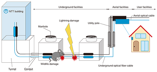
1. IntroductionWhenever an anomaly of any kind occurs in an optical fiber cable, its cause is investigated using the transmission alarms received and reports submitted by customers. An optical-pulse test device called an optical time domain reflectometer (OTDR) is generally used to locate faults outside NTT buildings. The underground, aerial, and user facilities making up the optical access network outside NTT buildings are shown in Fig. 1. The waveforms obtained from OTDR measurements can be used to find out where among these facilities the fault occurred. Details about the fault°«s location can then be clarified by comparing these measurements with facility-layout drawings. If the state of damage can be examined visually, then repairs can be made quickly. However, if a fault occurs in an underground conduit, then determining the conditions is more challenging. In gas-filled cables widely used for metallic wires, in which the cable is filled with gas for maintenance purposes, a gas alarm that signals a cable fault is generated if the cable°«s outer sheath is damaged. This alarm can be used to identify the segment containing the fault. However, most of today°«s optical fiber cables are non-gas cables, so it is difficult to determine in detail the damage to a cable°«s outer sheath at a fault point. This, in turn, makes it hard to determine whether damage to a cable°«s outer sheath will soon cause a fault in the optical fiber within the cable. Therefore, the process of deciding when a cable should be renewed takes time. Examples of such cable faults are ones caused by wildlife and lightning, which are on the increase [1], [2].
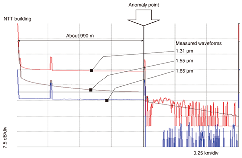
This article introduces a probing method that can easily and rapidly identify the position and cause of a fault in an optical fiber cable located within an underground conduit. 2. New methodOur new probing method for determining the position of a fault occurring in an optical fiber cable within an underground conduit combines two existing techniques: an OTDR test and a pipe camera investigation. (1) OTDR test OTDR waveforms are used to find the fault position in a faulty fiber. The position (distance) of the fault from the NTT building and the nature of the fault (cut fiber or bending loss) can be determined by interpreting these waveforms. An example of waveforms for a faulty optical fiber is shown in Fig. 2. Anomalies at a distance of about 990 m from the NTT building can be analyzed.
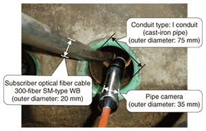
(2) Pipe camera investigation Once the manhole nearest the fault point has been identified from the OTDR test results and facility data, a pipe camera can be lowered into that manhole and inserted into the target conduit, as shown in Fig. 3. The images obtained from the pipe camera can then be used to determine conditions within the conduit and to identify the position (distance) and cause of the fault in the field.
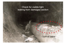
In this process, visible light is injected from the NTT building into the fibers of the optical fiber cable under inspection. If the outer sheath of the optical fiber cable has been damaged and an optical fiber within the cable has been cut, images obtained from the pipe camera will show visible light leaking from that optical fiber through the outer sheath at the location of the cut (Fig. 4).
3. Field experimentTo assess the utility of the probing method, we conducted an experiment in the field. The experimental setup is shown in Fig. 5. For this experiment, we laid a 300-fiber SM-type WB (Single-Mode fiber, Water-Blocking) cable with a total length of about 110 m and created an artificial cut-fiber fault at a distance of about 30 m from manhole #1. The results of probing for the fault position using the new method are summarized below.
(1) From the OTDR waveforms in Fig. 2, we determined that a fiber cut had occurred about 990 m from the NTT building. When we checked the facility data, we found that the manhole nearest this location was manhole #1 (about 30 m away). (2) Next, we inserted the pipe camera shown in Fig. 3 into the target conduit and inspected cable conditions from the obtained images. We found that the cable was damaged at two locations near the 30-m point from manhole #1. The distance counter mounted on the pipe camera revealed that these two damaged sections lay at distances of 26.0 and 26.4 m from manhole #1. (3) Finally, we injected visible light into the faulty optical fiber to check for any light leaking from that fiber (Fig. 4). As a result of inspecting the cable at the two damage locations determined by the pipe-camera inspection, we found that light was leaking at one of them. This demonstrated the effectiveness of the new method. 4. ConclusionA new method using an OTDR and a pipe camera together with a visible-light source provides a straightforward and speedy means of clarifying cable conditions within a conduit and identifying the position and cause of faults. The obtained information can be used to decide on a suitable response to take such as replacing the cable and the urgency of that response. References
|
|||||||


