 |
|||
|
|
|||
|
Global Standardization Activities Vol. 9, No. 1, pp. 50–55, Jan. 2011. https://doi.org/10.53829/ntr201101gls Standardization Trends for Optical Transport Network Technologies in ITU-TAbstractIn this article, we explain recent standardization trends in ITU-T SG15 WP2 (International Telecommunication Union, Telecommunication Standardization Sector; Study Group 15; Working Party 2) for optical transport network technologies such as optical transmission and optical fibers and cables to support the increase in data traffic resulting from new services using the optical broadband network and the evolution of high-speed Ethernet.
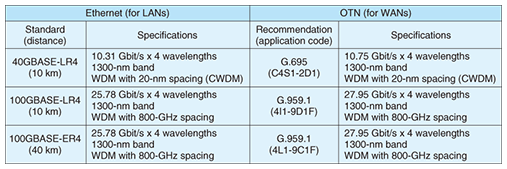
1. BackgroundWorking Party 2 (WP2) in ITU-T SG15 (International Telecommunication Union, Telecommunication Standardization Sector; Study Group 15) is responsible for standards for optical transport network technologies including network infrastructure, systems, equipment, and optical fibers and cables and their related installation, maintenance, and measurement techniques. WP2 is currently handling seven Questions; their titles are as follows. Q5: Characteristics and test methods of optical fibers and cables Q6: Characteristics of optical systems for terrestrial transport networks Q7: Characteristics of optical components and subsystems Q8: Characteristics of optical fiber submarine cable systems Q16: Optical physical infrastructure and cables Q17: Maintenance and operation of optical fiber cable networks Q18: Development of optical networks in the access area The international standards related to these fields play an important role in the development of the industry. Here, we focus on the 40G/100G optical interface (40G and 100G are names denoting data transmission rates that are close to 40 and 100 Gbit/s, respectively), optical transmission to support the evolution of FTTx (fiber to various different termination points), etc., which are hot topics these days. 2. High-speed Ethernet and OTN optical interfaceQ6 is responsible for developing standards for optical interfaces for terrestrial transport networks, excluding the access network. First, we explain high-speed Ethernet and the related optical interface for the Optical Transport Network (OTN). Ethernet is standardized in IEEE802.3ba and its main target is local area networks (LANs). On the other hand, OTN is standardized in ITU-T and its main target is wide area networks (WANs). A high-reliability, high-capacity, long-distance optical transport network based on wavelength division multiplexing (WDM) technology can be achieved by using OTN technology. 40G Ethernet and 100G Ethernet were standardized in June 2010. Their notable feature is multilane transmission such as 4 × 10G and 4 × 25G. The standards for Ethernet targeted at single-mode fiber (SMF) transmission are listed in Table 1. OTN currently has four line rates defined by optical channel transport units (OTUs). The OTU4 frame, which can accommodate a 100G Ethernet signal transparently, was standardized in ITU-T Recommendation G.709. The OTU frame is composed of a payload, overhead for administration, and bits for forward error correction. The bit rate of the OTU4 frame is 111.8 Gbit/s. Optical interfaces for parallel transmission of 40G and 100G signals based on G.709 were standardized in Q6 with a view to enabling the utilization of Ethernet optical modules considering demands for low costs. Recommendation G.695 specifies the optical interface for coarse WDM (CWDM) and a new application code was added for 40G, 10-km transmission using four wavelengths, which is related to 40G Ethernet. The bit rate carried by each wavelength is 10.75 Gbit/s (10.75 Gbit/s × 4 wavelengths). Recommendation G.959.1 specifies an inter-domain interface for optical networks and new application code was added for 100G, 10-km and 40-km transmission using four wavelengths, which is related to 100G Ethernet. The bit rate carried by each wavelength is 27.95 Gbit/s (27.95 × 4 wavelengths).
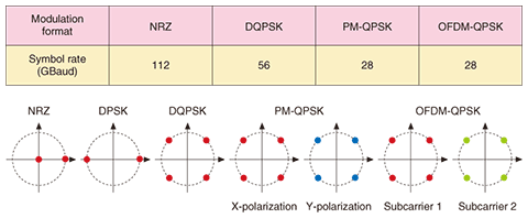
3. 40G/100G high-speed optical interfaceThe modulation format in optical transmission systems that has been considered so far in ITU-T is non-return to zero (NRZ). NRZ is a binary on-off keying that represents a digital signal 0 or 1 according to the intensity of the optical signal. However, in serial high-speed, long-distance transmission of 40 Gbit/s or more, it is important to improve receiver sensitivity, wavelength dispersion tolerance, and polarization mode dispersion (PMD) tolerance, so various modulation formats have been researched and developed to overcome these problems. Against this background, Q6 started to investigate new modulation formats in 2007 and, as a result, differential phase shift keying (DPSK), differential quadrature phase shift keying (DQPSK), polarization-multiplexing QPSK (PM-QPSK), which is also called dual-polarization QPSK, orthogonal frequency division multiplexing (OFDM), etc. were added to Supplement G.Sup39 in 2008. Note that G.Sup39 is not a Recommendation but describes design and engineering considerations for optical transmission systems as a supplement. DPSK is a binary phase modulation in which phase differences of 0 and π between adjacent optical signals correspond to digital signals 0 and 1, respectively. It can increase the receiver sensitivity by approximately 3 dB. DQSK is a four-level phase modulation in which phase differences of 0, π/2, π, and 3π/2 correspond to digital signals 00, 10, 01, and 11, respectively. It can not only increase the receiver sensitivity but also transmit two bits per signal. This means that it can halve the required electrical interface speed, or in other words, it allows a transmission capacity that is double the symbol rate. DQPSK has the advantage of increasing the wavelength dispersion tolerance, PMD tolerance, and spectral efficiency. PM-QPSK is a format that combines QPSK with polarization division multiplexing. It can reduce the symbol rate to one quarter. If digital coherent technology is used in the receiver, the sensitivity is more than 3 dB higher, and waveform distortion due to wavelength dispersion and PMD can be compensated for electrically. In OFDM, several subcarriers are generated and multiplexed in the frequency domain. OFDM can decrease the symbol rate in proportion to the number of subcarriers. The symbol rates and constellation diagrams of several modulation formats are shown in Fig. 1, for OTU4 (112 Gbit/s) as an example. In a constellation diagram, the x and y axes represent the in-phase and quadrature-phase components of the signal, respectively.
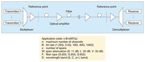
40G systems using DPSK or DQSK have recently been introduced in optical metro and backbone networks on the market. 40G optical interfaces with new modulation formats are currently being examined in ITU-T, especially with the aim of conforming to Recommendation G.698.2, which provides optical parameter values for the physical layer interfaces of DWDM systems intended primarily for metro applications including optical amplifiers, targeting multi-vendor compatibility. Q6 has started to discuss how to specify an extinction ratio and an eye mask in terms of phase modulation because new specifications are needed for them. The standard for 100G serial optical interfaces has also been discussed in ITU-T. The addition of 100G application code to Recommendation G.696.1 (an NTT proposal) was given consent in the plenary meeting in June 2010. G.696.1 provides physical layer specifications for intra-domain DWDM systems targeting longitudinally compatibility. A configuration example of a multi-span DWDM system and its application codes are shown in Fig. 2. The application code previously had only four bit rates: 1.25G, 2.5G, 10G, and 40G. It was extended to 100G for the first time. The characteristics of a 100G signal using the PM-QPSK format and digital coherent detection are described in Appendix I of G.696.1 as an application example.
Another topic that Q6 is treating is all-optical networks. Recommendation G.680 defines a degradation function for optical network elements considering impairments such as optical noise and chromatic dispersion. This Recommendation is now targeting reconfigurable optical add-drop multiplexers (ROADMs). Q7 is responsible for the standard for the characteristics of optical components and subsystems. The latest topics include PMD compensators and optical components for phase modulation systems. Moreover, Q8 has considered revising two Recommendations on the characteristics of repeaterless optical fiber submarine cable systems (G.973) and optically amplified optical fiber submarine cable systems (G.977) in response to increases in transmission capacity. It has also considered revising the Recommendations on optical fiber submarine cables (G.978) and test methods applicable to optical fiber submarine cable systems (G.976), which are needed for constructing and operating the systems because they need to provide higher service reliability. In recent years, the assurance of interoperability has become one of the most important issues. A new Recommendation, G.973.1, for longitudinally compatible DWDM applications for repeaterless optical fiber submarine cable systems was created in November 2009. Q8 intends to continue discussing system interoperability in order to provide systems that are more cost effective. 4. Optical fibers and cablesThe characteristics of optical fibers used for current SMF communication have been defined in five Recommendations: G.652–656. So far, Q5 has created and revised some Recommendations on optical fibers, e.g., optimization of descriptions of chromatic dispersion characteristics of G.65x fibers, in synchronization with considerations on optical transmission technologies in Q6. The characteristics of SMF, which is most generally used in current optical access and core networks, are defined in G.652. When SMF is bent with a bending radius of several tens of millimeters, it suffers from optical bending loss at bend. Therefore, the development and standardization of bending-loss insensitive fibers have received broad attention. In response Q5 created Recommendation G.657 on the characteristics of the bending-loss insensitive SMF for access networks in 2006. At that time, a major topic of discussion was a bending-loss insensitive fiber that allowed a bending radius of 15 mm, which is half the allowable bending radius of conventional SMF. In December 2009, Q5 created the second edition of G.657, which covers bending-loss insensitive fiber that allows a bending radius of 5 mm, in response to a request to support the provision of cost-effective unskilled optical fiber distribution. In general, there is a trade-off between the bending loss characteristics and the mode field diameter (MFD) for SMF. If the bending loss characteristics are improved, the MFD becomes smaller, which in turn causes an increase in the connection loss. Therefore, as listed in Table 2, G.657 defines fiber categories considering compatibility with the conventional SMF and minimum allowable bending radii. There are four fiber categories. Standardization of category A3 has been continuously discussed along with the research and development of bending-loss insensitive fibers. Another important issue is to clarify the mechanical reliability of optical fibers bent with a small radius, so Q5 revised the appendix of G.657, which deals with the reliability of optical fibers. In Q5, discussion of reliability is now underway in cooperation with Q16 and the International Electrotechnical Commission (IEC).
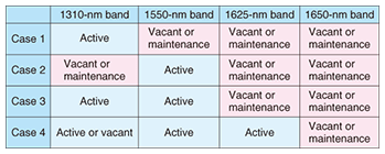
Q5 has also studied test methods for SMF (G.650.1–650.3). G.650.1 and 650.2 deal with test methods for linear and nonlinear attributes of SMF, respectively. These are used to evaluate SMF transmission characteristics. G.650.3 deals with test methods for transmission lines. Further discussion about such test methods is expected for the development of FTTx as the use of optical fibers grows. On the other hand, recommendations for various optical fiber cables have been studied in Q16. Recommendation L.87 on an optical drop cable consisting of bending-loss insensitive fibers defined by G.657 was created. This was in response to a request to support the installation of small-bending-radius optical fiber cables. The drop cable allows an aesthetic and flexible distribution of optical fiber cables in subscriber premises. L.87 describes the characteristics and construction and test methods (mainly following IEC standards) of optical fiber cables for drop applications. Q16 decided to ask IEC SC86 WG3 to standardize test methods for cables bent with a small radius because there was a comment about the need for test methods in the course of the discussion. 5. Optical fiber cable networksQ17 has examined recommendations related to the maintenance and operation of optical fiber cable networks. Recommendations L.25, 40, and 53 define fundamental requirements for optical fiber network maintenance, an optical fiber testing system, and maintenance for passive optical networks and ring networks, respectively. Moreover, recommendations related to the allocation of a maintenance wavelength and maintenance criteria for in-service fiber testing in access networks are described in L.41 and 66. Table 3 shows which communication bands have maintenance wavelengths allocated in them as defined in L.41. In-service fiber testing can be conducted irrespective of the service type by using 1650 nm (in the U-band) as the maintenance wavelength even when bands O–L (1260–1625 nm) have been allocated to service provision.
An optical fiber identification technique is important in maintaining network reliability and operating an optical fiber network effectively. It lets us distinguish the target fiber from among many fibers. Q17 created Recommendation L.85 on this optical identification technique in July 2010. As shown in Fig. 3, this Recommendation describes the method specified in this Recommendation using a non-destructive macrobending technique. An identification light is injected into the target fiber from the end of an optical fiber line (e.g., a central office) or is introduced by using optical devices for testing (e.g., an optical coupler). This identification light has a different wavelength from the communication light carrying the data signal. The optical fiber identifier bends the optical fiber, and a photodetector located at the center of the bent part detects the modulated identification light leaking from the bent fiber. L.85 defines requirements for optical fiber identification, which were based on L.41 and 66 for in-service line testing.
Q17 is also studying requirements for systems that monitor outside plant facilities. It is planning to create Recommendations for natural disaster countermeasures for outside plants. Q18 is studying a configuration for passive optical networks (PONs), which have become a major topology class for optical access networks. A Recommendation for providing cost-effective efficient FTTx is expected because this is an important global issue. In response to a request, Recommendation L.86 describing considerations on installation sites for branching components in PONs for FTTH (fiber to the home) was published in 2010. 6. Future effortsITU-T SG15 WP2 is currently undertaking a wide range of activities such as producing a handbook containing outlines of Recommendations created by WP2. NTT will continue to contribute to international standardization of optical transport network technologies including optical transmission technology, which will have higher-speed interfaces in line with optical network evolution, and optical fiber line technologies. AcknowledgmentThe efforts to have the 100G serial optical interface technology adopted as an international standard are partly supported by the Universal Link Project of the National Institute of Information and Communications Technology (NICT) of Japan. |
|||


