 |
|||||||||||||||||||||||||||||||||||||||||||||
|
|
|||||||||||||||||||||||||||||||||||||||||||||
|
Regular Articles Vol. 9, No. 2, pp. 63–68, Feb. 2011. https://doi.org/10.53829/ntr201102ra1 Optical Control of Nanomechanical Vibration in GaAs ResonatorsAbstractVibrational control in GaAs micromechanical cantilevers through optical carrier excitation has been demonstrated. With laser irradiation to [110]-oriented cantilevers at near-band-gap wavelengths, the quality factor increased with increasing laser power, whereas shorter-wavelength irradiation decreased the quality factor. The opposite laser power dependence was observed for [-110]-oriented cantilevers (90°Ž different). These results indicate that the control of the quality factor is due to the piezoelectric stress generated by optically excited carriers. This is a new method of controlling nanomechanical vibration in micromechanical resonators, which does not need any cavities or feedback circuits.
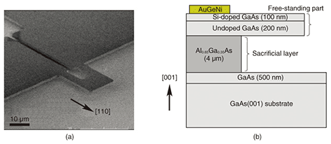
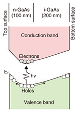
1. IntroductionMicromechanical and nanomechanical resonators have been extensively used for a wide variety of applications, such as sensors, actuators, and filters [1], [2]. The quality factor (Q-factor) is an important factor determining the sensitivity and performance of micromechanical resonators. It is inversely proportional to the damping; i.e., the vibration of a low-Q resonator is rapidly damped while that of a high-Q resonator lasts longer. Controlling the damping and the Q-factor is of great importance in many micromechanical device applications. One effective method is feedback control of micromechanical resonators by using electrical and optical circuits. Feedback Q-control has been applied to high-sensitivity measurements, such as atomic force microscopy and magnetic resonance force microscopy [3]–[6]. Another approach to Q-factor control involves coupling micromechanical resonators to light in optical cavities. Cavity-induced radiation pressure and photothermal pressure enable us to modify the Q-factor as well as the resonance frequency of micromechanical resonators [7]–[18]. These methods have been used in practical micromechanical devices, but they need a feedback circuit or a carefully aligned optical cavity. Here, we describe our carrier-excitation-based Q-factor control in micromechanical resonators [19]. This method has potential as an alternative to conventional Q-control methods because the Q-factor of micromechanical resonators can be controlled by simply adjusting the wavelength and power of the incident laser light. The micromechanical resonators used in this experiment were made of GaAs, which is a direct-band-gap semiconductor exhibiting piezoelectricity [20]. These material properties are essential for this optical Q-control method. 2. ExperimentalThe micromechanical cantilevers were fabricated by molecular beam epitaxy crystal growth, photolithography, and etching [21]. A scanning electron micrograph of a fabricated cantilever is shown in Fig. 1(a). The cantilever was 20 μm long and 14 μm wide, including two legs 10 μm long and 4 μm wide. It consisted of a 100-nm-thick Si-doped (n-type) GaAs layer and a 200-nm-thick undoped (i-type) GaAs layer, which were grown on a 4-μm-thick Al0.65Ga0.35As sacrificial layer on a GaAs(001) substrate (Fig. 1(b)). The n-type layer had a temperature-independent carrier concentration of 1.5 × 1018 cm-3 and electron mobility of 1900 cm2/Vs. This cantilever had a built-in electric field, as illustrated in Fig. 2, due to the impurity doping and the surface depletion. The sacrificial AlGaAs layer was selectively removed with hydrofluoric acid and then the free-standing structure was completed using supercritical drying [21]. AuGeNi electrode pads were sintered onto the supporting part to form an ohmic contact with the n-GaAs layer. We prepared cantilevers oriented along the [110] and [-110] directions to study the dependence of orientation on the resonance characteristics.
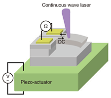
Fabricated cantilevers were mounted on piezo-actuators (Fig. 3) and set in the vacuum chamber of a 4He cryostat with a small window allowing optical access to the sample. The mechanical resonance characteristics were electrically measured by the following piezoresistive method (Fig. 3): (i) Sinusoidal voltage (6 mVrms) was applied to the piezo-actuators while the frequency was swept around the resonance frequency of the fundamental vibration mode. (ii) Constant current (30 μA) was applied to the cantilevers and the frequency response of the resistance change (piezoresistance) was measured by monitoring the voltage difference with a spectrum analyzer. (iii) The resonance characteristics were measured by illuminating the center of each cantilever’s free-standing part with continuous-wave laser light. A He:Ne laser and a tunable Ti:Sapphire laser beam with a 4-μm spot were used to study the wavelength dependence of the damping in the range λ = 633–840 nm.
The Q-factor of the cantilevers, given by Q =
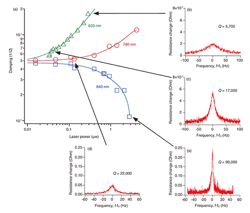
3. Results and discussionFigure 5 shows the relation between the damping factor and laser power for several wavelengths and the mechanical resonance characteristics of the [110]-oriented cantilever measured for several laser powers at those wavelengths. The sharpness of the resonance peak depended strongly on the incident laser power. The laser power dependence of the damping is shown in detail in Fig. 5(a). The damping increased with increasing laser power for λ = 633 nm; e.g., the Q-factor was reduced by a factor of three when the intensity was increased from P = 0.04 μW (Fig. 5(c)) to 0.29 μW (Fig. 5(b)). The damping also increased with increasing laser power for λ = 780 nm, which is still shorter than λBGi (Fig. 5(a)). Note that, for this wavelength, the laser power dependence of the damping was much weaker than that for λ = 633 nm, as shown in Fig. 5(a). Interestingly, we found that when the incident wavelength was λ = 840 nm, which is in the range of λBGi <λ< λBTn, increasing the laser power decreased the vibration damping (Q-1) (Fig. 5(a)). For λ = 840 nm, drastic enhancement of the Q-factor from 22,000 to 90,000 can be clearly seen in Figs. 5(d) and (e). These results demonstrate that the Q-factor can be widely altered by changing the power and wavelength of the incident laser. We did not observe any change in the Q-factor for λ = 860 nm (λ > λBTn). This suggests that the change in Q-factor was caused by photogenerated electron-hole pairs in the cantilever.
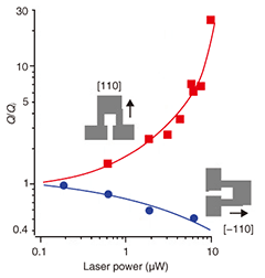
To study the physical mechanism of the optical Q-factor control, we investigated its cantilever orientation dependence. The Q-factor normalized by the intrinsic Q-factor (Qi) is plotted in Fig. 6 as a function of laser power in [110]- and [-110]-oriented cantilevers for λ = 840 nm. In the [110]-oriented cantilever, higher laser power enhanced the Q-factor. In contrast, in the [-110]-oriented cantilever, higher laser power decreased it. This behavior suggests that the change in Q-factor is not dominated by radiation pressure or photothermal pressure [5]–[16].
Here, we focus on the piezoelectric stress due to the photovoltaic effect because the piezoelectric constant d31 is opposite in sign to that of d32; i.e., the piezoelectric stress should work oppositely in the [110] and [-110] orientations in the zincblende structure [17]. Thus, once electric dipoles have formed in the growth direction ([001]), they induce piezoelectric stress in the longitudinal direction, where the stress is compressive or tensile depending on the cantilever orientation. Optically excited carriers generate such electric dipoles because holes in the valence band drift toward the cantilever surfaces, whereas electrons gather at the bottom of the conduction band located in the i-GaAs layer owing to the built-in electric field (Fig. 2). This spatial charge separation is the cause of the piezoelectric stress, which provides the bending motion that influences the mechanical vibration of the cantilever (i.e., backaction). If this backaction enhances the vibration in the [110]-oriented cantilever, it oppositely damps the vibration in the [-110]-oriented one because the direction of the piezoelectric stress is opposite in the latter. By analogy with optomechanical damping produced by Fabry-Perot cavities [17], there are two requirements for this optical Q-factor control: (i) The backaction force should act on the cantilever with a certain time delay with respect to the cantilever’s motion and (ii) the amplitude of the backaction force should vary depending on the cantilever’s displacement. The photovoltaic effect due to the optical excitation satisfies the first requirement because carrier drift and electron-hole recombination take finite lengths of time. The photovoltaic effect can also meet the second requirement if the optical absorption coefficient changes with the cantilever’s deflection. The deformation potential and piezoelectric potential in GaAs can provide such a deflection-dependent optical absorption property. This deflection dependence will be pronounced when the incident laser wavelength is near the absorption-edge wavelength, while it will be weaker for shorter wavelengths because of the large absorption coefficient. Thus, we consider that the change in Q-factor at λ = 840 nm is due to the piezoelectric stress induced by carrier excitation. For shorter-wavelength excitation, some other factors may dominate the vibration damping. 4. ConclusionsWe have demonstrated Q-factor control by carrier excitation in micromechanical cantilevers consisting of n- and i-GaAs layers. For laser irradiation to a [110]-oriented cantilever at near-absorption-edge wavelengths, the Q-factor increased with increasing laser power, while shorter-wavelength irradiation decreased the Q-factor. The opposite behavior was observed for a [-110]-oriented cantilever. This difference suggests that the Q-control is due to piezoelectric stress generated by optically excited carriers. This Q-control method is a promising alternative to the conventional methods because it does not need either external feedback loops or high-finesse cavities. AcknowledgmentsWe thank Daisuke Ito (now in Sony, Japan) for help with sample fabrication and measurement. This work was partly supported by Grants-in-Aid for Scientific Research (Kakenhi) from the Japan Society for the Promotion of Science (20246064 and 19310067). References
|
|||||||||||||||||||||||||||||||||||||||||||||


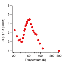
 f0/Δf, where f0 is the resonance frequency and Δf is the full width at half maximum of the resonance peak, was derived by fitting the resonance power spectrum with a Lorentzian function. Figure 4 shows the temperature dependence of the intrinsic Q-factor (Qi), which was measured without laser illumination. Qi was maximum at 50 K, where the value was about 4.5 times higher than that at 300 K (Qi (300K) ~4000). This is because the thermal expansion, which causes the thermoelastic damping effect, was minimized at 50 K [21]. Optical control of the Q-factor was demonstrated at 50 K, where the photothermal effect became negligible. At 50 K, the resonance frequency of the cantilevers was 240 kHz and the band-gap wavelength for i-GaAs was λBGi = 820 nm [20]. The n-GaAs layer had a conduction-band tail (Fig. 2), resulting in wavelength λBTn, which corresponded to the energy difference between the tail edge and the top of the valence band, of 850–860 nm [20].