 |
|||||||||||
|
|
|||||||||||
|
Regular Articles Vol. 9, No. 2, pp. 69–74, Feb. 2011. https://doi.org/10.53829/ntr201102ra2 Ray-tracing-based Technique for Reducing Computational Complexity of MIMO Propagation Channel EstimationAbstractWhen radio areas or systems in wideband wireless communication systems are being planned, a multiple-input multiple-output (MIMO) propagation channel must be considered. This article introduces a technique based on ray tracing that reduces the computational complexity for estimating the MIMO propagation channel. This technique can estimate the MIMO propagation channel without any increase in the computational complexity when the number of antenna elements is increased.
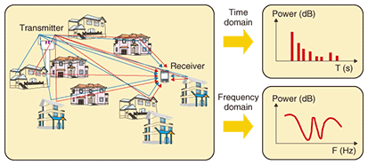
1. IntroductionIn wireless communication systems, wireless signals from a transmitter are transmitted to a receiver via multiple propagation paths. As shown in Fig. 1, the ground and buildings cause reflection, diffraction, or penetration in these paths. As a result, radio waves taking different propagation paths arrive at the receiver at different times and each propagation path has a different phase condition since it has a different path length. Therefore, at the receiver, different received power levels are observed for each frequency. This frequency selective fading, as it is called, has a tremendous impact on the communication quality of wideband wireless communication systems. Therefore, propagation characteristics including frequency selective fading must be considered when service areas or systems in wideband wireless communication systems are being planned. There are various methods for estimating propagation characteristics. The ray-tracing method [1] is one of the most well known and most effective methods for estimating the propagation characteristics in multiple-input multiple-output (MIMO) systems. However, MIMO propagation channel estimation by ray tracing requires an enormous amount of calculation resources. In this article, we introduce a ray-tracing technique for overcoming the computational complexity, which is a major problem in MIMO propagation channel estimation.
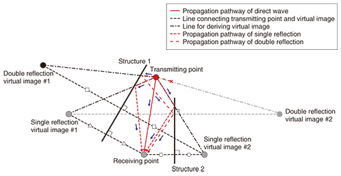
2. Ray-tracing method and its issues2.1 Ray-tracing methodAlgorithms for the ray-tracing method are classified into two general types: the imaging method and ray-launching method. The imaging method derives a propagation path by using geometric optics from a combination of the transmission position, receiving position, and reflecting surfaces. On the other hand, the ray-launching method derives the propagation path using rays discretely launched at given regular intervals and searching for the rays that arrive at the received position. Estimating the propagation characteristics using the ray-tracing method requires three parameters: the propagation distance, incident angle to the reflecting surface, and complex permittivity of the reflecting surface. The propagation distance and the incident angle to the reflecting surface are derived from ray-tracing estimation results. The complex permittivity of the reflecting surface is a predetermined static parameter. 2.2 Issues facing ray tracingAs shown in Fig. 2, the ray-tracing method derives the propagation path including reflection, diffraction, and penetration from the transmitter to receiver using geometric optics. The estimation accuracy can be improved by increasing the number of reflections, diffractions, or penetrations in the case of the imaging method or by increasing the number of rays launched from the transmitter in the case of the ray-launching method. However, the receiving area must be configured for propagation channel calculation by the ray-launching method since there is a very low probability that rays launched from the transmitter will arrive at the receiving point. Moreover, it is quite complicated to decide the receiving area. Therefore, in this article, we focus on the imaging method in order to introduce our new technique.
In the imaging method, it is necessary to search for the propagation path for the combination of all allocated building walls. Thus, in the case of single-input single-output systems, one must judge whether a reflection point exists on the wall a total of AB times when the number of building walls is set to A and the number of reflections is set to B. For instance, as shown in Fig. 2, a single reflection requires two judgments and a double reflection requires four. The computational complexity increases with the square of the number of walls, reflections, diffractions, and penetrations. Therefore, many computational complexity reduction techniques have been studied. 2.3 Special problem in applying ray tracing to MIMO systemsMIMO technology, which uses multiple antennas at the transmitter and at the receiver to improve the transmission rate, has recently been widely studied. IEEE 802.11n (IEEE: Institute of Electrical and Electronics Engineers) and WiMAX (worldwide interoperability for microwave access), which are recently standardized wireless schemes, both use MIMO technology. MIMO propagation channel evaluations that use the ray-tracing method have been reported. However, whether a reflection point exists on a wall must be judged a total of m × n × AB times when an m × n MIMO system is treated. Thus, there is the additional problem that the computational complexity increases in proportion to the number of antenna combinations when the ray-tracing method is applied to MIMO systems. 3. New technique for reducing calculation complexity for MIMO propagation channel estimation3.1 Special characteristics of MIMO propagation channelIn general, a MIMO propagation channel simulation is performed under the condition that the physical sizes of the transmitter and receiver array antennas are much smaller than the distance between the transmitter and receiver antennas. Under such a condition, as shown in Fig. 3, the propagation paths between all the transmitter and receiver antenna elements are often extremely similar. Thus, to decrease the computational complexity, it is generally thought that a MIMO propagation path can be simulated by using the propagation path between a particular combination of antennas instead of those for all the transmitter and receiver antenna combinations.
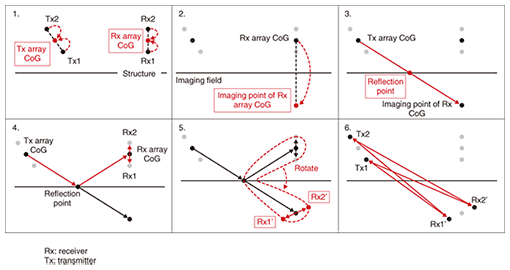
3.2 New techniqueOur new technique uses the abovementioned MIMO propagation channel characteristic to simulate a MIMO propagation channel for the propagation path between a particular combination of transmitter and receiver antennas instead of those for all antenna combinations. The procedure for deriving the propagation distance using this technique for a single-reflection wave in a 2 × 2 MIMO system is shown in Fig. 4.
The procedure is as follows.
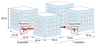
In our technique, a shorter distance between a particular antenna position and another antenna position is better considering the estimation error. Thus, desirable antenna positions for a particular combination are the CoGs of the transmitter and the receiver array. Our technique attempts to decrease the propagation distance estimation error by using information about the positional relationship between the array CoG and each array element. The reflection and diffraction angles in our technique are defined as the same angles as derived by ray tracing between the transmitter and receiver COGs. This is because the propagation paths between all transmitter and receiver antenna elements are often extremely similar to the results of ray tracing between the transmitter and receiver CoGs. 3.3 Special features of our techniqueBecause our technique focuses on decreasing the computational complexity of the path search, it can be applied to not only the imaging algorithm but also the ray-launching algorithm. Moreover, it further decreases the computational complexity by combining previously proposed ray-tracing acceleration algorithms because they are mainly focused on efficient path searching. 4. Verification based on simulation model4.1 Simulation model and parametersThe propagation channel calculated using the ray-tracing method is derived using the propagation distance, reflection or diffraction angle, and electrical properties of the wall. The wall’s electrical properties are represented by a fixed parameter. On the other hand, since the propagation distances and reflection or diffraction angles calculated using our technique are approximated parameters, there is some mismatch between the values of these parameters calculated by our technique and by conventional ray tracing. Therefore, the MIMO propagation channel estimation error was evaluated from the difference between the eigenvalue calculated using the imaging algorithm and that using our technique because the parameter provides a good representation of the effect of the phase difference of each element. A MIMO propagation channel simulated using the outdoor simulation model is shown in Fig. 5. A four-element transmitter antenna array and a four-element receiver antenna array were used. As shown in Fig. 5, a 4 × 4 MIMO propagation channel was calculated using the imaging algorithm and our technique at positions ranging from Y= 0 m to 30 m at intervals of 1 cm. The calculated frequency was 2.45 GHz. The maximum number of reflections was set to three, and the number of diffractions was set to one for the ray-tracing calculation. Only the reflected wave and the diffracted wave were treated in the simulation model for verifying our technique. When propagation characteristics are simulated using the ray-tracing method, a penetration wave may need to be considered. However, our technique is effective even when the existence of a penetration wave is taken into consideration.
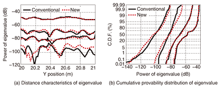
4.2 Simulation resultsAn example of the variability of the eigenvalue characteristics obtained using the imaging algorithm and our technique for positions from Y=20 m to 21 m in the simulation model is shown in Fig. 6(a). The value of each eigenvalue calculated using the imaging algorithm could be reproduced by our technique. The cumulative probability of each eigenvalue in the whole simulation section calculated using the imaging algorithm and our technique is shown in Fig. 6(b), which shows that the distribution was almost the same for all eigenvalues compared with those for the imaging algorithm and our technique. Therefore, these results show that a statistical evaluation of the MIMO propagation characteristics calculated using the imaging algorithm can be reproduced using our technique.
With our technique, as the number of antennas is increased, the benefit of the reduced computational complexity increases. This is because the path search process accounts for the majority of the computational complexity in the conventional ray-tracing method. In general, when the number of antenna elements is increased, our technique can estimate the MIMO propagation channel without any increase in computational complexity. For instance, when 4 × 4 MIMO is assumed, the number of antenna combinations is 16. Therefore, the computational complexity for our technique is approximately 1/16 (6.25%) of that for the conventional ray-tracing method. For the simulation model and conditions, it is 6.30% [4]. 5. ConclusionMIMO technology is essential to current wireless communication systems. In this article, we described a technique for overcoming the computational complexity, which is a major problem in MIMO propagation channel estimation using ray tracing. Our technique can estimate the MIMO propagation channel without any increase in computational complexity when the number of antenna elements is increased. In the future, we will continue to evaluate propagation characteristics with our technique and improve it for practical use so that it can handle various wireless communication systems. References
|
|||||||||||


