|
|||||||||||||||||||
|
|
|||||||||||||||||||
       |
Regular Articles Vol. 9, No. 3, pp. 68–72, Mar. 2011. https://doi.org/10.53829/ntr201103ra1 Antenna Model and Its Application to System Design in the Millimeter-wave Wireless Personal Area Networks StandardAbstractThis article describes an antenna model developed for the system design and standardization of millimeter-wave wireless personal area networks (WPANs). It also discusses why a new antenna model is required for standardization activities. The developed antenna model is a simple mathematical analog. It provides a main-lobe pattern and averaged side-lobe level by setting the antenna’s half-power beamwidth. This model was adopted as a reference antenna model in the channel model document of the IEEE 802.15.3c millimeter-wave WPAN task group. 
1. IntroductionWireless systems, such as cell phones, wireless local area networks, and wireless personal area networks (WPANs), have come to be widely used in our lives. These systems will also play an important role in future home networks. On the other hand, with the rapid progress of information and communications technologies, including high-performance personal computers (PCs) and high-speed Internet access lines like fiber to the home, the data sets being handled by consumers, such as video and music files, are drastically increasing in size year by year. Therefore, wireless systems are being pressured to support high-speed data transmission with gigabit-per-second-class data rates. One practical way to achieve such high-speed wireless systems is to allocate and use the huge bandwidth available in the millimeter-wave band. When these systems are used in home networks, technology standards are required because home networks consist of devices provided by many vendors. This article focuses on an antenna model developed for the standardization of millimeter-wave WPANs and discusses why a new antenna model had to be developed. The antenna model is a simple mathematical analog and provides a main-lobe pattern and averaged side-lobe level by setting the antenna’s half-power beamwidth. It enables comprehensive system design by considering signals arriving from all directions including behind the antenna. 2. WPANsWPANs are consumer-oriented short-range wireless communication systems linking personal devices. They were originally developed as low-rate communication systems for connecting a mouse and/or keyboard to a personal computer, a car navigation system to a cell phone, and a music player to a set of headphones. They were found to be a very cost effective way of linking devices. Two widely used WPAN technologies are Bluetooth and ZigBee. A very wide frequency band near 60 GHz has been or will be allocated as an unlicensed band in many countries. Examples are 59–66 GHz in Japan, 57–64 GHz in the USA, Canada, and Korea, and 57–66 GHz in European countries and Australia. This band is a good candidate for achieving ultrafast WPAN systems suitable for future home networks. To take advantage of the broad unlicensed bandwidth in the 60-GHz band, several standardization activities are focusing on developing standards for this band [1]. The 60-GHz-band WPAN system is promising for supporting uncompressed high-definition video streaming and ultrafast downloading of huge files from a server, namely kiosk file downloading. 3. Propagation channels of millimeter-wave WPANsAll wireless systems use radio waves that propagate through the air. The radio waves are reflected by walls and diffracted by obstacles. As a result, the receiver captures scattered signals that arrive from many directions with different time offsets. This propagation environment yields the propagation channel or simply channel. The propagation channel strongly affects system performance. Hence, accurate modeling of it is important in designing new wireless systems. A typical example of WPAN usage is schematically shown in Fig. 1. A transmitter and receiver are located in a small room. The sofa, chairs, table, and cabinet act as obstacles. Signals from the transmitter are reflected and diffracted by the walls and obstacles. They arrive at the receiver from different directions with different time offsets. In this multipath environment, the delayed signals can improve the system performance as well as degrading it. In a typical standardization process, several systems are proposed, and their performances are evaluated and compared in order to narrow down the proposals to only one. In this process, each proposer must use the same channel model so that comparisons are correct and fair. Therefore, standardization task groups for wireless systems must define the channel model before calling for proposals.
For millimeter-wave WPAN system construction, one must use a directional antenna because of the high propagation loss of millimeter-wave signals and their low transmission power, which is strictly limited by law. The signal power received by the directional antenna is strongly influenced by its antenna pattern and is a significant determiner of system performance. Thus, WPAN system design requires antenna pattern evaluation as well as a channel model. 4. Antenna model for millimeter-wave WPAN system designBeside the regulatory constraints, design goals such as low power consumption also dictate low transmission power for WPAN systems. Since millimeter-wave signals have high propagation loss, the use of a directional antenna is essential. As described in section 3, WPAN systems are usually used in multipath environments, so a system design must consider signals arriving from outside the antenna’s main lobe. The requirements of the antenna model used for WPAN system design are summarized as follows: (1) Model antennas with half-power beamwidths of 15–60°, which are common in WPAN systems. (2) Include side-lobe effects. (3) Cover antenna patterns defined over 360°. (4) Provide a simple mathematical model that simplifies system simulation. Among these requirements, (2) and (3) are unique to WPAN systems because of their use in multipath environments. Many antenna models have been developed and used for the design and evaluation of various wireless systems [2], [3]. Here, we introduce a new antenna model suitable for WPAN system design. The basic concept is shown in Fig. 2. The red line shows the antenna pattern of a typical directional antenna. The blue line shows the antenna pattern of the design model. The horizontal axis plots the angular offset from the direction of antenna peak gain and the vertical axis plots antenna gain. As shown in this figure, the design model has a constant side-lobe level. Actual performance of a designed wireless system depends on room size, room shape, locations and number of obstacles, and transmitter and receiver locations. Hence, system design is performed for several typical cases using statistical channel models [4]. The channel model is created from measured data in some environments and is used to statistically generate signals arriving at the receiver. That is, the generated signals are not exactly identical to real signals. This means that exact side-lobe patterns are unimportant and the averaged side-lobe level is more practical for this application even though the actual antennas do not have constant side lobes.
There are two ways to determine the side-lobe level. One way is to consider practical applications. For example, in the case of interference assessments, the design side-lobe level is set a little bit higher than the actual side-lobe level. This provides conservative results for interference analyses. However, the antenna model described in this article is intended for new systems that include PHY/MAC (physical layer, medium access control) specifications. Thus, using this conservative approach may cause significant error because the side-lobe effects depend on the specifications. The other way of determining the side-lobe level is to derive it from physical requirements, i.e., the conservation of energy law. We averaged the power outside the main lobe to obtain a side-lobe level that satisfies the physical requirements. The averaged side-lobe level Gsl can be expressed as 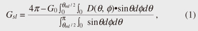 where G0, D(θ, φ), and θml are the peak gain, directivity function normalized by the peak gain, and main-lobe angular width, respectively, and θ and φ are polar coordinates. The second term of the numerator is the total power included in the main lobe. The denominator is the integration over the solid angle outside the main lobe. This expression ensures that the total radiated power i.e., the integration of the antenna pattern, is kept at 4π. To calculate this equation, we must determine G0, D(θ, φ), and θml. Our approach uses, as the directivity function of the main lobe, a Gaussian function of only θ owing to its simplicity. This means that the modeled antenna has a rotationally symmetric beam. G0 is calculated from the theoretical response of the circular aperture antenna, which has a similar main-lobe pattern to the Gaussian beam antenna. θml is determined by the angle at which the main-lobe function decreases by -20 dB from its peak. Equation (1) is not easy to calculate in a system simulation because its integration is difficult to solve analytically. Our solution is to derive an approximate expression using the results of a numerical integration. The developed antenna model is formulated in terms of directivity gain G(θ, φ) as follows: [5]   where θ-3dB is the antenna’s half-power beamwidth and θ-3dB is in units of degrees. Equations (2) and (3) give the directivity gains of the main and side lobes, respectively. Here, the directivity gain is not a function of φ, which means that the antenna has a rotationally symmetric beam. Antenna patterns calculated using the design model and measured patterns for rectangular horn antennas are shown in Fig. 3. As shown in this figure, the main-lobe patterns of the design model agree well with the measured ones. The side-lobe levels of the model are constant and well approximate the average values of the measured patterns. Thus, the antenna model is effective in millimeter-wave WPAN system design.
5. ConclusionThis article elucidated the role of antenna models in millimeter-wave WPAN standardization. Antenna patterns along with channel models must be considered in order to achieve fair and correct assessment of new wireless systems that use directional antennas because WPAN systems are commonly used in multipath environments where signals come from many directions. The antenna model described in this article is a simple mathematical analog with constant side-lobe level that reflects the average value. This feature is suitable for designing millimeter-wave WPAN systems. The antenna model has been adopted as a reference antenna model in the channel model document of the IEEE 802.15.3c millimeter-wave WPAN task group [6]. AcknowledgmentThis work was conducted as part of the discussions in the antenna working group of the Consortium for Millimeter Wave Practical Applications (CoMPA). We thank all of the CoMPA members for their comments. References
|
||||||||||||||||||