 |
|||||||||
|
|
|||||||||
|
Regular Articles Vol. 9, No. 6, pp. 29–35, June 2011. https://doi.org/10.53829/ntr201106ra1 Cabling Technologies Providing More Optical Cabling Potential in Multi-dwelling Unit BuildingsAbstractFor optical access services to multi-dwelling units (MDUs), we have developed compact optical splitter modules that provide greater installation flexibility and indoor optical cabling that can be installed on the building’s exterior walls. They overcome problems encountered in providing optical fiber cabling systems to MDUs and installing splitter modules in the limited space available in main-distributor-frame boxes as well as other difficulties caused by a lack of space in conduits or the absence of conduits.
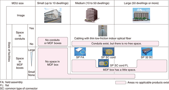
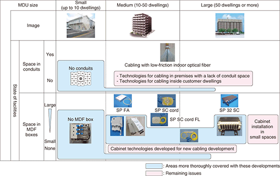
1. IntroductionIn June 2010, the number of fiber-to-the-home (FTTH) contracts in Japan surpassed 18 million, heralding the age of ubiquitous optical fiber access. However, since roughly 40% of all households in Japan live in multi-dwelling units (MDUs), such as apartment buildings and condominiums [1], there is growing demand for more adaptable optical cabling systems to provide fiber to households in these sorts of dwellings. In contrast to FTTH cabling schemes for detached houses, which consist of a 4-branch optical splitter in the central office and 8-branch splitter module parts (SPs) installed on the user side (supporting 32 subscribers), schemes for MDUs and office buildings use 32-branch SPs (or a cascade of one 4-branch SP followed by four 8-branch SPs). To date, thin low-friction indoor optical fiber [2] that enables more cables to be installed in conduits and SPs that can be installed in the empty spaces scattered throughout customer buildings (e.g., telephone conduits and main distribution frame (MDF) boxes) [3] have been developed and deployed to expand the range of available cabling systems. They have helped to reduce the number of MDU buildings unsuitable for optical fiber cabling. However, as indicated in Fig. 1, many medium-sized and large MDU buildings have a lack of empty space available in existing MDF boxes etc., and the metallic nature of the hardware already installed means that the conventional SPs cannot be installed easily, and many small MDUs have no conduits or MDF boxes. These conditions make it difficult to provide optical-fiber-based services to such buildings. To tackle these problems, we have developed (1) technologies for installing SPs in MDF boxes in medium-sized MDU buildings, (2) cabling that can be installed on the exterior walls of small MDU buildings, and (3) technologies for installing SPs in large MDU buildings.
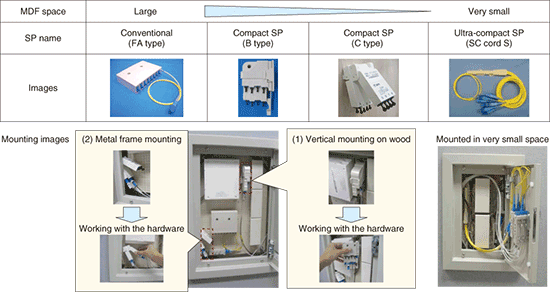
2. SP installation technologies for medium-sized MDU buildingsSince the SP hardware needs to be small enough to fit into the limited space available in existing MDF boxes, we developed a range of smaller SPs that includes both an ultra-compact SP that can be installed in very small MDF boxes and compact SPs designed to provide better workability and allow more flexible installation methods (Fig. 2). These are described below.
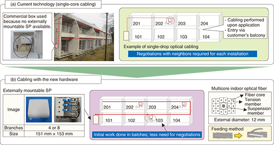
2.1 Ultra-compact SPFor SP installation in very small spaces, we further miniaturized the existing SP (called the SC cord FL (flat), shown in Fig. 1) [2]. An overview of the new SP (SC cord S (small/stick)) is shown in Fig. 2. By devising a way to fit the splitter section inside the casing, we reduced the space required for installation by 20%. We also developed multiple alignment members that can be fitted to individual cores, which protect the fiber core connections used for feeding the cord to subscriber residences. 2.2 Compact SPsIn dealing with the increasingly diverse cabling forms that result from cabling schemes in optical connection systems used for feeding single-core cable (single-drop optical fibers etc.), it is more efficient to assemble a cable sheath fixing connector (plug type) and terminate it directly at the SP. Moreover, there is a growing need for more versatile attachment methods that do not rely on only ordinary screws, but also enable attachment to metal or plastic. Our new compact SPs (B and C types) are overviewed in Fig. 2. We reduced the space required to maneuver the hardware and install an SP by including input and output sockets and by eliminating the cord section. Unlike conventional equipment where the connectors are secured with screws, these SPs use magnetic attachment to the SP and hinged SP mechanisms. The new design enables much easier detachment and attachment and greatly simplifies the connection work required inside small MDF boxes. 3. External wall cabling technology for small MDUsSome small condominiums do not have an MDF box or conduits available for cabling subscribers desiring optical fiber services. In this situation, a commercially available box is usually attached to the exterior of the building and the SP is installed inside it. Cabling enters the subscriber’s home via the balcony, but this means that work is performed when each individual residence applies for subscription, and negotiations with neighbors are required for permission to work on communal walls (Fig. 3(a)).
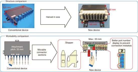
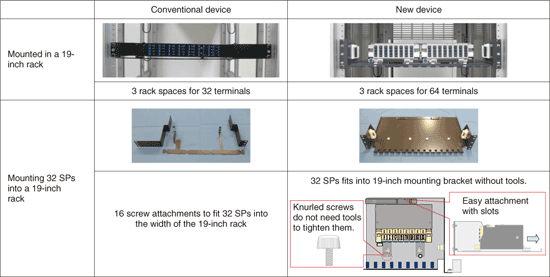
To address these problems, we have developed a compact box-type SP for attachment to building exteriors and indoor optical fiber bundles that eliminate the need for repeated negotiations with neighbors after the initial application for work. An overview of the hardware is shown in Fig. 3(b). We used the casing for two existing compact attachable boxes (PD and SS types) and it opens and closes in the same way. We designed the units to be resistant to ultraviolet (UV) light and water in order to be suitable for external installation. The indoor optical fiber bundle is a cable consisting of 8 UV-resistant indoor optical fibers pre-twisted helically with suspension members. When an optical fiber is fed into a subscriber residence, one of these optical fiber cores is selected and connected to the sheath grip connector (FA (field assembly) connector [3]) and then laid. These systems can reduce the need for problematic negotiations with neighbors about service connection work. 4. SP installation technologies for large MDUsIn cases where there are a large number of prospective users in a large MDU, it is more efficient to batch-install 32-branch SPs rather than the cascades of 4- and 8-branch SPs usually installed in small and medium-sized MDUs. For large MDUs, in addition to installations in the empty space in MDF boxes, there is also demand for 19-inch rack-mounted SPs. Conventional 32-drop SP units are the same height as one 19-inch rack unit (1U), but taking into consideration the space required for maneuvering the input and output cabling, each one needs 3U of free space. Moreover, the installation of more than one conventional 32-drop SP (e.g., to handle 64 or more terminals) in a 19-inch rack requires the use of more than 3U. Therefore, it would be desirable to have more compact hardware that can be installed in a standard 19-inch rack and can make better use of the space available. To ensure enough work space, we reconsidered the pitch between the usual connectors and chose to use a modular scheme that enables the connector sections to be moved horizontally in and out of the chassis. Simply sliding the required section to insert a connector ensures the same level of workability as with the conventional devices. We also designed a simple 19-inch rack installation method that does not require the use of specialized tools, unlike the usual hardware that requires many screw attachments to add an expansion SP. An overview of the hardware is shown in Fig. 4. The new device that we have developed (SP 32 SC-S (slide/small)) fits in half the space required for the conventional device, so two of them, supporting 64 subscribers, can be installed in the 3U required to install and work on one conventional unit supporting 32 subscribers.
We also developed a 19-inch mounting bracket for the SP 32 19-inch rack installation (Fig. 5) to which the unit is secured by simply sliding it into position and securing with only two screws at the front. We think that it could reduce work time by up to 80%. We have also aimed for better workability by using knurled screws for tool-free tightening by hand and keyhole-type slot-in screw holes.
5. Further plansThese new cabling technologies can improve workability and expand the service provision coverage. However, although the uptake of optical fiber services such as FLET’S HIKARI continues at a phenomenal rate, it does not mean that 100% of services can be provided to all subscribers. As shown in Fig. 6, further work is needed to expand services to areas not covered by these new developments. With these new technologies as a base, we plan to continue working to develop indoor cabling technologies that can be applied to all MDUs as well as technologies that streamline the installation work required for optical fiber access services.
References
|
|||||||||


