 |
|||||||
|
|
|||||||
|
Feature Articles on Technical Solutions to Real-world Problems Vol. 9, No. 7, pp. 7–10, July 2011. https://doi.org/10.53829/ntr201107fa1 Simulation System for Estimating Hazardous Voltages Induced in Telecommunication Cables by Power FaultsAbstractThis article introduces a system for simulating hazardous voltages induced in telecommunication cables in the event of power faults in high-voltage power transmission systems. When the estimated induction voltages exceed human safety limits, mitigation measures such as shielding the cables and using insulation (including the replacement of metallic telecommunication cable by optical fiber) are required. However, to date most of the work of calculating and estimating induced voltages has depended on manual operations. The new simulation system greatly reduces most of the manual operations by using a personal computer and a telecommunication cable database.
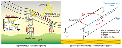
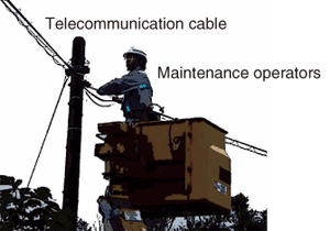
1. IntroductionPower faults in high-voltage power transmission lines can be caused by lightning, typhoons, and power-line insulation breakdown, as shown in Fig. 1. Figure 1(a) shows a power fault current flowing to the ground after a power fault was caused by lightning. Figure 1(b) shows the mechanism of power induction between a power line and a telecommunication cable running parallel to it. When a power fault occurs, a high electromagnetic field can be generated by the power fault current. This field also generates electromagnetic induction ac (alternating current) voltages in the telecommunication cable. When a maintenance operator touches the telecommunication cable, as shown in Photo 1, after a power fault has occurred, the operator receives a shock from the ac voltage induced in the telecommunication cable. The induced voltage causes ac to flow through the operator’s body, typically via a hand. Such an electric shock can cause secondary accidents such as the operator being knocked over or falling to the ground and may even lead to death if the ac flow through the operator’s heart exceeds the safety limits.
To ensure the safety of maintenance operators, NTT and electric power companies have agreed to establish countermeasures for hazardous voltages caused by power induction. These agreements prescribe the calculation of induced voltage beforehand and the implementation of countermeasures whenever the voltage exceeds the limits shown in Table 1 [1]. The limits depend on the interruption time of the power fault. In the case of a high-stability power line having a short interruption time, the voltage induced in the telecommunication cable should be no more than 650 Vrms. In any case, the voltage induced in a telecommunication cable needs to be calculated beforehand, and if it exceeds the limits, countermeasures must be taken such as increasing the insulation on metallic cables, changing to a telecommunication cable with a high shielding effect, changing the routes of the telecommunication cables, or upgrading from metallic telecommunication cable to optical fiber.
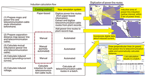
2. Problems with existing calculation methodsTo calculate voltages in telecommunication cables [2], we need the routes of power lines and telecommunication cables and also the power fault currents. The power line routes and power fault currents are given as paper-based maps and figures by the power companies. The telecommunication cable routes are obtained from NTT itself. The power-line and telecommunication-cable routes are on different maps, so these maps must be manually copied to a new map in order to obtain the distances between the power lines and telecommunication cables; this takes many hours per cable. Moreover, it has become increasingly difficult to build up knowledge about induced voltage calculation and induction countermeasures because employees with induction estimation skills are retiring and the in-house workforce is shrinking. This situation has generated a need for a tool that can estimate induced voltages simply while maintaining high accuracy. 3. Simulation systemOur new simulation system is compared with the existing method in Fig. 2. There are five steps in the procedure for obtaining induced voltage in telecommunication cables. (1) Gather power-line and telecommunication-cable route information. (2) Make a distance map of the separations between power lines and telecommunication cables. (3) Calculate mutual inductance between power lines and telecommunication cables from the distance map obtained in (2). (4) Calculate the power fault current. (5) Calculate the induced voltage.
In the existing method, steps (2)–(4) involve time-consuming manual operations. The maps of power lines and telecommunication cables are copied by hand, so high-level skills are required to reduce errors. When the number of telecommunication cable routes is high, e.g., 100 or 1000, it is hard to check all induced voltages for relevant telecommunication cables. By contrast, the new simulation system, which runs on a personal computer, is not based on manual operations and has three good characteristics: automatic preparation of the distances between a power line and telecommunication cables on the map, automatic calculation of induced voltage, and batch calculation of induction for all telecommunication-cable routes. 3.1 Automatic preparation of distances on mapThe first step in the existing method is to acquire information about power-line routes (from paper maps) from the power company and manually overlay that information onto the NTT paper-based plant record. The next step is to project perpendicular lines from the power line to sections of the telecommunication cable using rulers and squares and to calculate the average distance for each section. By contrast, the new system enables power-line information on a paper map to be incorporated into an electronic telecommunication cable route database via a scanner and lets a user digitize coordinate data (latitude & longitude) of a power-line route by simply clicking on the route on a screen, thereby automating the creation of a map showing the distances between the power line and telecommunication cables (or routes). In this way, it is possible to automatically obtain a map of the separation distances along a power line (distance map), which in turn makes it possible to calculate mutual inductances between the power line and telecommunication cables automatically. 3.2 Automatic calculation of induced voltageVoltage induced in the telecommunication cable can be calculated by multiplying induced current (grounding current) by mutual inductance as computed from the distance map. In the existing method, induced-current values are also provided by the power company in the form of paper-based graphs. The new tool enables this graph data to be input into the system via a scanner so that induced-current values can be digitized by clicking on those data curves on the screen. This enables induced-current values needed for calculating induced voltage to be extracted automatically. 3.3 Batch calculation of induction for all telecommunication-cable routesThe new tool can also automatically determine whether any telecommunication-cable route is within the induction-impact range of a power line and simultaneously calculate induction for all telecommunication-cable routes in a batch. The operations needed to calculate and estimate induction can therefore be done much more efficiently. The precision of calculations is also improved through the use of map data that has not been input manually and is thus more accurate, which reduces the errors in induction estimation. 4. ConclusionNTT has developed a powerful new simulation system for estimating induction with a focus on hazardous voltages induced in telecommunication cables by power faults in high-voltage power transmission lines. This simulation system enables power-line routing information needed for calculating induced voltage to be digitized, thereby reducing computation time and improving computational accuracy. As a result, it has become possible to respond promptly to plans for raising voltage in power transmission lines, reduce dispersion in calculation results, and make more accurate decisions about the need to implement countermeasures to power induction. In fiscal year 2010, we used the results of field trials to improve the system’s workability and operability, and in response to the wishes of NTT branch offices involved in this trial, we implemented a function for estimating induced voltage from multiple power transmission lines. We also plan to implement a function for estimating voltage induced by other types of power-transmission systems such as in electric railways in addition to power transmission lines and investigate the networking of the induction-estimation tool to make calculations more efficient and to link databases. Our objective is to implement these enhancements in the field beginning in fiscal year 2011. References
|
|||||||


