 |
|||
|
|
|||
|
Feature Articles on Technical Solutions to Real-world Problems Vol. 9, No. 7, pp. 14–16, July 2011. https://doi.org/10.53829/ntr201107fa3 Troubleshooting Tool for FLET’S TVAbstractNTT EAST Technical Assistance & Support Center has developed a tool called the RF Checker for troubleshooting problems in the homes of FLET’S TV customers (RF: radio frequency). It can be used to check video-signal levels and video quality using simple operations, which should make in-home troubleshooting much more efficient.
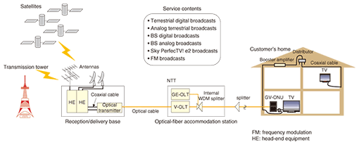
1. IntroductionFLET’S TV is a video broadcasting service that enables users to receive various types of broadcasts such as terrestrial digital broadcasts and BS (broadcast satellite) digital broadcasts through broadcast services offered by OptiCast Inc. via the FLET’S HIKARI optical fiber broadband service available from NTT EAST and NTT WEST. The FLET’S TV service model is shown in Fig. 1. First, the reception/delivery base receives video signals from satellites and terrestrial transmission towers via antennas and passes them to an optical transmitter after subjecting them to level adjustment, noise filtering, and other processes at head-end equipment. Next, the optical transmitter converts these electrical video signals to an optical signal, and transmits it. Finally, the NTT optical-fiber accommodation station amplifies and splits this optical signal at the video optical line terminals (V-OLTs), optically multiplexes it with an optical signal conveying FLET’S HIKARI communication signals from a Gigabit Ethernet OLT (GE-OLT) using an internal wavelength division multiplexing (WDM) splitter, and transmits them to a customer’s home over a single strand of optical fiber. At the customer’s home, an optical network unit (ONU) converts the WDM optical signals back to electrical video and communication signals. This ONU (GV-ONU) combines a V-ONU with a GE-ONU. The video signals arrive at television (TV) sets in the home via various types of wiring and devices such as coaxial cables, booster amplifiers, distributors, and branching filters.
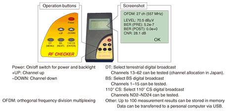
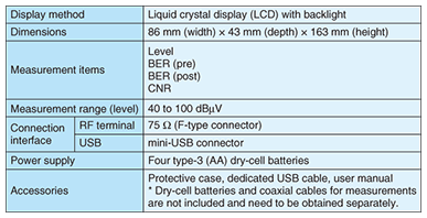
2. RF Checker2.1 Development backgroundSince its launch in July 2008, FLET’S TV has increased its subscriber base steadily and further growth is expected in the future. Moreover, while maintenance of the coaxial-cable section in the customer’s home was originally handled by the broadcasters, it was decided that NTT EAST and NTT WEST would take over maintenance for some users from March 2010 and April 2010, respectively. Therefore, NTT needed a means of performing prompt and accurate maintenance and troubleshooting in this coaxial-cable section. In response to this need, NTT EAST Technical Assistance & Support Center developed the RF Checker as a measurement tool that can be used by on-site technicians in the field to judge video quality even without specialized skills (RF: radio frequency). The RF Checker has the minimum necessary functions for measuring the quality of FLET’S TV in order to be an inexpensive and convenient handheld device that excels in operability and portability in the field. 2.2 FeaturesThe features of the RF Checker are summarized below (Fig. 2 and Table 1).
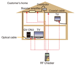
(1) Supports terrestrial digital, BS digital, and CS (communication satellite) digital (Sky PerfecTV! e2) (2) Measures the following items: íŽ Level íŽ BER (pre): bit error rate before correction íŽ BER (post): bit error rate after correction íŽ CNR: carrier-to-noise ratio (3) Evaluates measured values (level, BER, and CNR) on the basis of a threshold value and displays OK or NG (okay or no good). Threshold values may be set as desired. (4) Saves measurement results in internal memory (maximum 100 items) (5) Transfers saved data to a personal computer via a USB (universal serial bus) connection 2.3 UseThe RF Checker is operated as follows. It is turned on by briefly holding down the power-supply button and then connected to a coaxial cable (F-type connector) inside the customer’s home. Next, the button for the type of broadcast (terrestrial digital, BS, or CS) to be measured is pressed and a channel is selected by pressing the +UP or –DOWN button to begin automatic measurement. Results are displayed within a few seconds all together on one screen. They consist of level, BER (pre), BER (post), and CNR as well as OK or NG indicating whether those results are acceptable according to the threshold values. An on-site technician using the RF Checker during maintenance work can easily perform troubleshooting by measuring video quality at the GV-ONU video output terminal, at the coaxial terminal in each room in the coaxial-cable section, at the input/output terminals of the booster amplifier and distributors, or at the coaxial connector nearest to a TV. Actual troubleshooting begins from the TV side when video problems occur in only one TV set and from the ONU side when video problems occur in more than one TV set. Using the RF Checker, the technician can observe the display of OK or NG at multiple measurement points (or the display of “× under” instead of OK/NG in the case of a low level) and can conclude that a problem exists at the point where the display of OK/NG or “× under” changes. RF Checker usage points are shown in Fig. 3.
3. Concluding remarksThe RF Checker was released in February 2010. As of the end of March 2011, about 590 units are in use by the maintenance departments of NTT EAST and WEST and partner companies. Looking forward, we expect the number of problem incidents to increase as the use of FLET’S TV expands, but we also expect the use of the RF Checker as a troubleshooting tool inside customer homes to make repairs more efficient and raise the level of maintenance. |
|||


