 |
|||||||||||||
|
|
|||||||||||||
|
Regular Articles Vol. 9, No. 8, pp. 79–87, Aug. 2011. https://doi.org/10.53829/ntr201108ra2 Hyper Multi-point Satellite Communications System and Field Trial ResultsAbstractThis article presents our newly developed hyper multi-point data-gathering satellite communications system for enhancing the frequency utilization of satellite transponders and the results of field trials for evaluating its feasibility using the Japanese Engineering Test Satellite VIII. We have developed a prototype system that can collect various types of sensor data with high frequency utilization efficiency from a large number of data-sensing stations scattered over a wide area in a unified manner. The experimental results show that this system successfully collected sensor data having different characteristics such as frequency and data size simultaneously and efficiently.
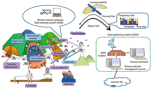
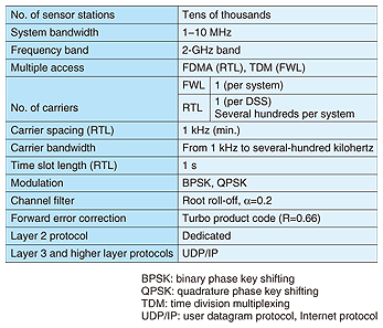
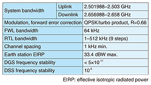
1. IntroductionSeveral natural disasters such as large earthquakes, giant tsunamis, and large hurricanes have recently occurred in the world and there is strong demand for a system that can predict the occurrence of natural disasters and reduce the damage inflicted by them. In meeting this demand, nationwide or region-wide sensor networks that gather environmental sensor data are expected to play key roles. Satellite communications has the inherent capability to offer a good solution for this type of application. However, conventional satellite communications systems cannot cope efficiently with small amounts of data transmitted from large numbers of data-sensing stations (DSSs). They waste satellite transponder bandwidth on small-size data because (1) conventional access control schemes, including both random access and demand assignment schemes, are inefficient at handling large amounts of small-size data and (2) guard bands that are wider than the data bandwidths are required because of the inadequate frequency stability of local oscillators in DSSs. To address these problems, we have proposed a hyper multi-point data gathering satellite communications system that offers highly reliable, extremely wide coverage and a cost-efficient sensor network infrastructure. To better utilize the satellite transponder bandwidth, our system uses dynamically assigned frequency division multiple access (FDMA) combined with a highly efficient and flexible channel allocation scheme. In this scheme, DSSs transmit signals using various frequency slots and time slots simultaneously. To receive/send such signals, a novel modem for a data-gathering station (DGS) that can demodulate hundreds of arbitrarily assigned multicarrier signals and a precise frequency control scheme for DSSs have been developed. This article describes our developed technologies and the results of field trials for evaluating system feasibility. 2. Hyper multi-point satellite communications systemThe concept is shown in Fig. 1, and major system features are listed in Table 1. The basic procedure of our system is as follows: (1) A sensor network management server administers the sensor network and knows DSS characteristics such as data amount and observation period. On the basis of these characteristics, the sensor network management server requests an access controller to assign a set of channels for the DSSs. (2) The access controller pre-assigns channel resources, i.e., time and frequency slots, to each DSS as a timetable, which is optimized by the optimal resource assignment algorithm. The DGS then sends the timetable to each DSS through the forward link (FWL) channel. The FWL channel is also used as a frequency and timing reference of the system. (3) The DSSs transmit their sensor data through the return link (RTL) traffic channel by referring to the abovementioned information provided by the FWL channel. (4) The transmitted data is finally aggregated by the sensor network management server, which delivers information to customers via terrestrial networks such as the Internet. To minimize the antenna size, equipment size, and DSS power consumption, a mobile satellite service band such as the S-band is preferable. Unfortunately, this band has a very limited bandwidth of 35 MHz. Therefore, the main feature of our system is that all DSSs, which synchronize their frequencies with a high degree of accuracy, can utilize a narrow bandwidth to gather a large amount of data efficiently. To achieve this, we have developed three novel technologies [1], [2], which are explained below:
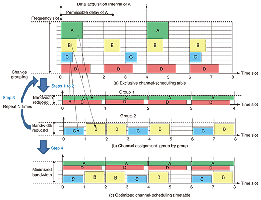
3. New technologies3.1 Channel allocation algorithmConsidering the number and variety of sensors involved, our channel allocation scheme must handle a wide variety of sensing data transmission characteristics while securing reliable transmission by avoiding data collisions on the satellite link. Major sensing data acquisition conditions were surveyed and are summarized in Table 2. There is a wide variety of data sizes and data acquisition intervals for each of the measurements taken. Data generation timing is roughly designated before data sensing begins. Consequently, it is hoped that channel pre-assignment will increase the frequency utilization efficiency and make it possible to accommodate more DSSs. As shown in Fig. 2(a), the simplest way of making the timetable is to pre-assign a channel exclusively to each DSS regardless of its data acquisition interval. This method, however, wastes the frequency and time slots. To effectively use the timetable°«s vacant slots, we rearrange the timetable by using an optimization algorithm. It uses a heuristic approach based on a multi-start local search [3] combined with the greedy method [4]. The procedure is as follows: Step 1. The transmission data is first classified into several groups depending on data acquisition conditions, and each group is assigned to a different number of time slots. Step 2. The transmission timing of each data item is moved within its permissible delay time to an appropriate frequency and time slot to minimize total transmission bandwidth by using the greedy method. This step is carried out group by group. Step 3. Steps 1 and 2 are repeated N times. At the same time, the multi-start local search is changing the data classification to reduce the total transmission bandwidth (see Fig. 2(b)). As a result, we can obtain the timetable shown in Fig. 2(c), in which the frequency and bandwidth of the transmitted signals are arbitrarily changed time slot by time slot. For example, with our algorithm, the number of unused frequencies and time slots in the timetable is less than 5% when the number of DSSs is more than ten thousand.
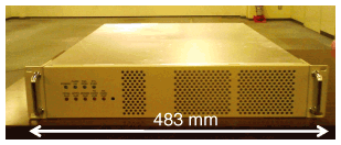
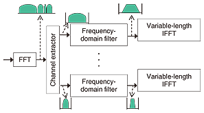
3.2 Dynamic and collective demodulationTo enable the demodulation of hundreds of arbitrarily assigned multi-carrier signals, a novel modem for the DGS was developed, as shown in Fig. 3. This modem°«s module uses a fast Fourier transform (FFT) type of block frequency demultiplexer as well as a multi-carrier burst modem with time-sharing operation. The principle configuration of the FFT-type block frequency demultiplexer is shown in Fig. 4. The received signal is converted into the frequency domain by FFT. Next, it is separated directly in the frequency domain and filtered. Finally, the separated components are individually reconverted to the time domain by using variable-length inverse FFT (IFFT). Arbitrarily and dynamically allocated signals are freely multiplexed in the frequency domain, and the variable-length IFFT circuits can handle hundreds of signals simultaneously with small-scale circuits.
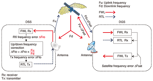
3.3 Frequency synchronizationTo control the transmission frequency of the DSS with high accuracy, and thus allow the guard band to be narrowed, we developed a frequency synchronization scheme, as shown in Fig. 5. First of all, the DGS receives its own FWL channel via a satellite. It then controls the FWL channel frequency by applying closed-loop transmission automatic frequency control to compensate for frequency error (ΔFsat) caused by the satellite transponder. As a result, the frequency error of FWL from the satellite becomes nearly equal to zero. Therefore, each DSS can detect the reception frequency error (ΔFro) of its own equipment by referring to the FWL frequency. The transmission frequency error ΔFto is deduced from ΔFro by multiplying ΔFro by the uplink/downlink ratio Fu/Fd, as shown in Fig. 5. Consequently, the transmission frequencies of all DSSs are synchronized with high accuracy. Moreover, the guard band can be narrowed without using special oscillators such as rubidium-based devices for each DSS.
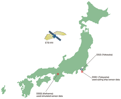
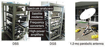
4. Field trial4.1 ConfigurationTo evaluate the system°«s feasibility, we have carried out field trials using the ETS-VIII (Japanese Engineering Test Satellite VIII) [5]. As shown in Fig. 6, two DSSs located 350 km apart were used to verify the technical feasibility. The DGS, DSS, and earth station antenna used in the test are overviewed in Fig. 7. To suppress the system cost, a temperature compensated crystal oscillator, which is generally used in cellular phones and has frequency accuracy on the order of 10-6, was used in each DSS. In the DGS, a rubidium oscillator was used to ensure highly accurate FWL signals. The access controller and the sensor network management server were connected to the DGS modem through the router.
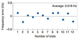
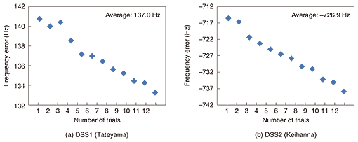
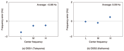
4.2 Frequency accuracyThe FWL frequency error at the DGS receiver input side is shown in Fig. 8. It is clear that the frequency error is less than 0.2 Hz. In the S-band, this frequency accuracy is on the order of 10-11. This result, therefore, shows that our technique achieves high FWL frequency precision by removing frequency error factors such as a satellite°«s Doppler shift. Next, ΔFro on DSSs detected from the FWL signal and the frequency error of the RTL signal of DGS input are shown in Figs. 9 and 10, respectively. In Fig. 10, L, M, and H on the horizontal axis show the center frequencies of the RTL, i.e., the bottom, middle, and top of the system bandwidth, respectively. In Fig. 9, we can see that ΔFro values were several hundred hertz and fluctuated over time. These errors are reasonable because the DSS°«s local oscillator stability was on the order of 10-6. Despite the large frequency errors in DSS, the RTL frequency errors at the DGS receiver input were within ±2 Hz. This frequency accuracy is on the order of 10-10. Therefore, the effectiveness of our technique was confirmed.
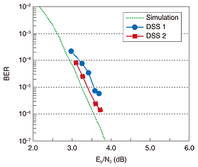
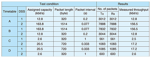
4.3 Transmission performanceSince the timetable (Fig. 11(a)), made out of seven time slots, was applied repeatedly, the spectrogram of the RTL signals shown in Fig. 11(b) indicates that each DSS successfully transmitted the RTL signal in sync with the timetable. The bit error rate (BER) characteristics of the RTL signal were measured under the condition that the bandwidth and frequency were dynamically controlled. As shown in Fig. 12, the degradation in BER characteristics, in terms of the ratio of the energy per bit to noise power spectral density (Eb/N0), was less than 1 dB compared with the simulation result. Packet transmission test results using four timetable patterns are shown in Table 3. Four timetables (A, B, C, and D) allocated different amounts of resources to DSS1 and DSS2, so that they achieved various throughput values. As we can see, all packets were received without any packet loss, and throughput was nearly equal to the allocated capacity. These results show that our system worked as expected and confirmed the system°«s effectiveness.
5. ConclusionWe carried out a field test of our hyper multi-point data gathering satellite communications system. The system features an optimal resource assignment algorithm for various types of sensor data, a highly accurate frequency synchronization scheme, and a dynamically assigned frequency division multiple access scheme. These enhance the frequency utilization efficiency of a satellite-aided sensor network. AcknowledgmentThis work is related to research sponsored by the Ministry of Internal Affairs and Communications through grants for °»Research and Development of the Highly Efficient Frequency Use Technique for the Communications Satellite Transponder°…. References
|
|||||||||||||


