|
|||||||||||||||||||
|
|
|||||||||||||||||||
       |
Feature Articles: Imaging and Sensing Technologies for Safety and Security Vol. 10, No. 2, pp. 8–13, Feb. 2012. https://doi.org/10.53829/ntr201202fa2 Millimeter-wave Imaging for Detecting Surface Cracks on Concrete Pole Covered with Bill-posting Prevention SheetAbstractIn this article, we introduce millimeter-wave imaging technology for detecting submillimeter-wide cracks under a bill-posting prevention sheet on a concrete telegraph pole. 
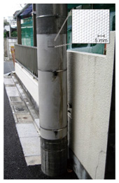
1. IntroductionNTT expends much effort in the long-term maintenance and management of the communication network to provide safe and secure communication services to customers throughout the country. Concrete telegraph poles, which are perhaps the most familiar of those facilities to most of us, are susceptible to physical damage, so a high degree of structural integrity is required. Concrete poles and other structures degrade over time; therefore, integrity maintenance requires periodic inspections so that degraded structures can be repaired. Since NTT owns more than ten million poles, such inspection is an every-day job for a large number of workers. Concrete poles carry cables, transformers, and other equipment that produces an unbalanced load on the structure over many years. The resulting bending stress produces fatigue cracking on the pole surface. When such cracking penetrates as far as the rebar inside the pole, rainwater may enter and cause corrosion that can lead to the rebar breaking. The steel rebar, which is strong in tension, is vital to balance the concrete, which is strong in compression but weak in tension, so broken rebar reduces the integrity of a concrete pole. Considering this degradation mechanism, we focused on the initial stage of degradation, which is the appearance of cracks on the concrete surface. NTT has experimentally verified that submillimeter-wide surface cracks have a high probability of reaching the rebar, so early discovery of the initial degradation is considered to be the best approach to structural integrity maintenance. Therefore, careful visual inspection of the pole surface is performed. NTT Access Network Service Systems Laboratories is developing a new technique to replace human visual inspection by using software to automatically detect cracks from images acquired by a digital camera. More details of that technique are given in the Feature Article “Detection of Cracks in Concrete Structures from Digital Camera Images,” in this issue [1]. To prevent unauthorized posting of advertisements on concrete poles, 2-mm-thick sheets of textured polyvinyl chloride (bill-posting prevention sheets) are bonded to the poles with acrylic resin in the region within reach by hand (Fig. 1). Exposing the covered surface for a visual inspection would require significant work to strip off the sheet and then replace it with a new one after the inspection. Since that would not be economically feasible, we conducted research and development (R&D) of a nondestructive inspection technique that allows observation of the condition of the pole surface without the need to remove the bill-posting prevention sheet.
2. Nondestructive inspection technologyMethods for seeing through the covering material to observe the condition of the surface beneath it are classified by the physical phenomena that are utilized. In particular, methods that use x-rays, ultrasonic waves, or microwaves have been applied in various fields. X-rays are a form of ionizing radiation that have high transmittance for materials other than water and heavy metals and allow imaging with micrometer-order spatial resolution. They are applied for medical purposes such as 3D imaging of internal organs and bones, but since they are harmful to humans, exposure levels must be carefully controlled: this would be a safety problem for workers using x-rays to inspect multiple concrete poles every day. Another problem is that practical x-ray imaging equipment is based on transmission, so it should really have a separate transmitter and receiver; however, for work sites with limited work space, reflection-based imaging equipment can be used. Ultrasonic waves are elastic waves*1 that have almost no effect on the human body and have high transmittance and millimeter-order spatial resolution for reflection-based imaging. They are therefore used for medical three-dimensional imaging of fetuses etc., but the procedure requires the application of grease between the ultrasonic wave transceiver and the object to be observed for efficient sound wave transmission. The expense of applying and removing grease would be a problem of the inspection of a huge number of poles. Microwaves are electromagnetic waves that have high transmittance and centimeter-order spatial resolution inside concrete, so they are used to inspect rebar. However, this technique does not provide the submillimeter-order spatial resolution required for crack detection, so imaging performance remains a problem.
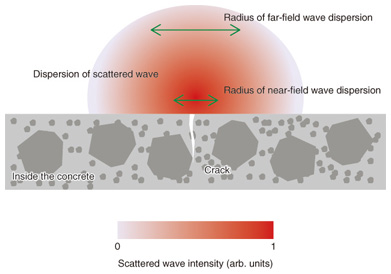
3. Millimeter-wave imaging technologyTo overcome the problems of safety, economy, and imaging performance, we took up the difficult R&D challenge of using millimeter waves, which are electromagnetic waves of higher frequencies than micrometer waves, to develop improved imaging technology. The millimeter-wave band includes frequencies from 30 GHz to 300 GHz, but the frequencies specified by the Radio Law for radar use (imaging is also one use of radar) range only from 76 GHz to 77 GHz (the band allocated to millimeter-wave radar). Considering the near future, the allocation of millimeter-wave radar band frequencies for inspection purposes is being studied. The main problems of concern in developing millimeter-wave radar technology for detecting cracks in concrete poles under bill-posting prevention sheets are 1) the transmittance of the plastic sheet, 2) submillimeter spatial resolution, and 3) the ease of equipment operation. In the band allocated for millimeter-wave radar, the relative permittivity of polyvinyl chloride is about 3 and the dielectric tangent is about 0.01, so if we assume a planar wave incident on a 4-mm-thick infinite plane, the attenuation due to reflection and propagation loss is low, about -10 dB, so transmittance is not a significant problem for equipment design. There is concern, however, that the texture of the bill-posting prevention sheet may have a greater effect on attenuation than the sheet’s material properties because of wave scattering at the surface. Another factor is that the width of the cracks to be detected is less than 1/10 the wavelength of the band allocated to millimeter-wave radar, so considering the radar cross-section area, the back scattering will be less than -30 dB relative to the power irradiating the surface. On the basis of the above estimates, we are investigating an equipment design in which the irradiation power of the millimeter-wave radiation is set to -50 dB to pass through the bill-posting prevention sheet to reach the crack and then pass back through the sheet again as back-scattering. Because the minimum beam diameter obtainable by focusing with a quasi-optical system using a lens is limited by diffraction, the beam width is limited to approximately the wavelength. The spatial resolution is therefore about half the wavelength, which means that it is difficult to detect submillimeter-wide cracks using the approximately 4-mm wavelength of the band allocated to millimeter-wave radar. For that reason, we have been trying to improve the spatial resolution by detecting near-field scattering. The concept, as shown in Fig. 2, is that the spatial resolution can be improved because the waves scattered from the crack, which can be regarded as a minute point in a cross-section that includes the crack width direction and the crack depth direction, are spherical waves*2. The dispersion of the scattered waves is thus small in the near field. Detecting near-field scattering with submillimeter-order spatial resolution requires the use of an antenna whose aperture is equivalent to the width of the scattered waves at the detection height. We are therefore investigating aperture design at the antenna placement height with consideration given to operability.
Inspecting all of the concrete telegraph poles in the entire country for structural integrity requires highly efficient work. The shortest imaging time could be achieved by covering the entire bill-posting prevention sheet with the antenna for detecting near-field scattering that is needed in the detection of submillimeter-wide cracks, but it is difficult to arrange antenna elements at submillimeter intervals in the crack width direction. Even if the elements were arranged at millimeter intervals, since the bill-posting prevention sheet is about 1.5 m long in the vertical direction, the number of antenna and millimeter-wave transmitter and receiver components would be huge and the equipment cost would be uneconomical. The equipment would also be large, which would reduce its portability. To maintain economy and portability, we considered a method in which ten antennas are arranged in a one-dimensional array in the crack length direction and the array is scanned in the crack width direction. Spatial resolution in the crack width direction is maintained by detecting scattered waves at submillimeter intervals. The equipment can perform multiple scans in the crack length direction in order to image the entire surface.
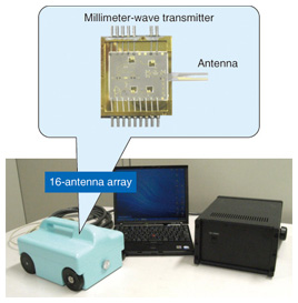
4. Concrete pole inspection equipmentOn the basis of the design policy described above, we constructed portable equipment (CP Scan) for detecting cracks in concrete poles under bill-posting prevention sheets (Fig. 3). Sixteen intensity-phase detection modules having tapered slot antennas are arranged in a one-dimensional array. A signal from the module is input to the baseband circuit at submillimeter scanning intervals in sync with a signal from an encoder attached to the wheels of the unit: in this way, the condition of the concrete pole surface is imaged. The case containing the module, encoder, and baseband circuit weighs less than 4.1 kg and can be held in one hand for scanning. The entire system, including the power supply and personal computer, weighs less than 10 kg and can be carried by a single person. The 16 modules can image an 8-cm-wide path in a single scan, and one or two workers can inspect a pole in about three minutes by making five or six scans to completely image the entire region of the bill-posting prevention sheet (Fig. 4).
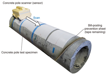
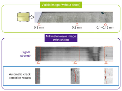
5. Feasibility of submillimeter-wide crack detectionTo test the practicality of the CP Scan, a bill-posting prevention sheet was attached to a concrete pole that had been removed for renovation (Fig. 5) and the CP Scan was used to inspect this area. The pole had cracks ranging in width from 0.3 mm to 0.15 mm. Although this preliminary experiment was suitable for confirming the method’s principle, the attached bill-posting prevention sheet was not bonded to the pole. The scanning rate was 120 mm/s with data being acquired at intervals of 0.2 mm in the scanning direction. That rate will allow one concrete pole to be inspected in about three minutes. A millimeter-wave image was obtained after three scans (Fig. 6). Although the equipment must be calibrated, the imaging only requires the equipment to be kept tightly against the pole during the scan, so the operation is simple.
To allow a single person to perform the inspection, as shown in Fig. 5, the power supply and personal computer parts of the system must be small and light, and image processing is essential for automatic crack detection from the acquired images. Therefore, NTT Access System Laboratories is currently developing an algorithm suitable for millimeter-wave image analysis. These experiments used the Crack Scan automatic crack detection software that was subject to hard disclosure commissioning to Airec Engineering Corporation in 2008 for evaluation of the detection characteristics. The red solid lines in the bottom row of Fig. 6 indicate cracks detected by the Crack Scan automatic detection algorithm, confirming that 0.15-mm-wide cracks can be detected. These results open up the prospect of developing portable equipment that can detect cracks that are at least 0.15 mm wide with a scanning time of about three minutes per pole. 6. Future plansIn future work, we will test the system’s practicality on actual poles with bill-posting prevention sheets bonded to them and evaluate the detection performance with our automatic crack detection software for millimeter-wave images of concrete poles. We will continue conducting R&D that will have wide applicability with highest priority on ease of operation and higher inspection efficiency while achieving practical detection performance suitable for equipment that can be used in actual concrete pole inspection work. References
|
||||||||||||||||||