|
|||||||||||||
|
|
|||||||||||||
       |
Feature Articles: Imaging and Sensing Technologies for Safety and Security Vol. 10, No. 2, pp. 14–18, Feb. 2012. https://doi.org/10.53829/ntr201202fa3 Detection of Cracks in Concrete Structures from Digital Camera ImagesAbstractIn this article, we introduce an image processing technique for detecting fine cracks in concrete poles by examining remotely acquired photographs. 
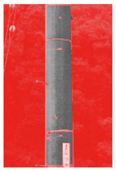
1. IntroductionNTT has many concrete structures as communication infrastructure facilities and it performs periodic inspections of them for safety maintenance and management. Those structures include a particularly large number of concrete poles, so efficient inspection is essential. The on-site inspection for cracks in the concrete surface of a concrete pole is meticulous because cracks allow rainwater to enter and corrode the rebar inside, which reduces the strength of the structures. Current crack inspection methods mainly involve human visual inspection, but it is difficult for workers to maintain concentration over a long period of work, and even skilled inspectors can overlook fine cracks. In particular, when inspecting concrete poles for cracks, workers must use binoculars rather than the naked eye and continuously focus on locations that can be ten meters high or higher. This is fatiguing, which also makes it difficult for the workers to maintain concentration. Furthermore, the number of inspectors is decreasing year by year and this has increased the workload per worker. These circumstances necessitate increased efficiency in crack inspection through automation of on-site inspections. From the viewpoint of ease of handling and operation of equipment, remote photography of structures with digital cameras and automatic crack detection from the obtained images by software is an effective approach. In this article, we describe the most recent image processing algorithms that have overcome technical problems for practical use. 2. Difficulty of crack detection by image processing techniquesAlgorithms for automatic detection of cracks from images of concrete surfaces have already been proposed, but the existing methods have problems in terms of practicality. In efforts to detect cracks by image processing, cracks are generally defined using edge features, regardless of the algorithm used. Cracks are represented as sharp changes in gray-scale values between edges and adjoining pixels that form an outline and appear in images as darkened lines. Thus, edges are the unique feature that indicates cracks. These algorithms are effective for images that include only concrete surfaces, but they do not work well when the image also includes extraneous obstacles. The reason for the poor performance in practice is that images of actual on-site concrete structures often include obstacles such as windows and sashes in the case of buildings and cables or foot pegs in the case of concrete poles. The edges formed by the outlines of such obstacles can be mistaken for cracks. An example of results produced by commercial crack detection software is presented in Fig. 1. The pixels colored red indicate areas judged by the software to be cracks, and we can see that the background, belts, plates, and other edges were erroneously detected as cracks. To overcome this problem, it is necessary to eliminate such obstacles from the image before performing the crack detection processing. However, it is not easy to obtain a highly accurate solution with current pattern recognition techniques because of the infinite variety in obstacle shapes. Accordingly, extracting only the cracks from images that include such obstacles has been very difficult.
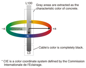
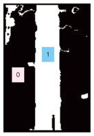
3. Obstacle removal algorithmBecause various obstacles exist at the site of actual facilities, as mentioned above, it is not easy to eliminate obstacles by defining their shapes and creating an algorithm to remove them directly. Therefore, with our algorithm, we chose to take the opposite approach of indirect obstacle removal. The indirect approach involves extracting the pole’s concrete surface and inverting the results. We explain the main points of the algorithm below. First, we extract from the input image pixels that seem to represent concrete surface. Because the concrete surface is generally gray, we can use a color system such as the one shown in Fig. 2 to represent color chrominance numerically and extract the gray pixels, which have low chrominance values. In the color classification results (Fig. 3), the pixels that are nearly gray are made white and pixels that are not close to gray are made black. This image has a green forest as the background, so color classification can be used to identify the rough outline of the concrete pole, but if the image contains a gray structure, the concrete pole can be identified by the amount of texture. It was therefore necessary to supplement the color information with texture information as explained below in order to extract concrete pole surfaces from various types of images with greater certainty.
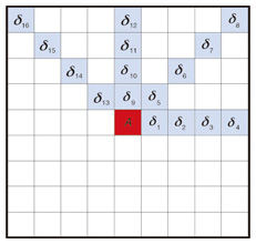
The concrete surface, which consists of cement and fine grains of sand, has a characteristically rougher texture pattern than other materials usually found in images. We know the pole’s roughness pattern and can thus distinguish concrete pole from other gray objects. This surface roughness pattern is referred to as texture in image analysis terminology, and it is used in judging materials. In our algorithm, we obtain a numerical value for the texture feature S of the concrete surface by calculating the homogeneity of 16 pixels in a pattern around a particular pixel, such as the light blue pixel formation (δ1 to δ16) around the red pixel A in Fig. 4. The specific method used to calculate the texture feature is described in Ref. [1].
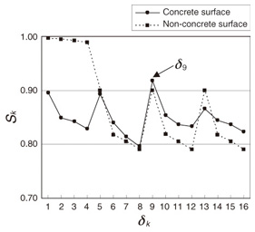
Calculating the homogeneity for the 16 pixels produces 16 texture values, Sk (k=1, 2, …, 16). The relation between δ and S is plotted in Fig. 5, where the solid line represents the calculated results for the concrete surface and the broken line represents the calculated results for non-concrete surfaces. As we can see from the figure, the shape of the graph differs greatly for concrete and non-concrete surfaces. It is therefore possible to determine whether or not a pixel is part of a concrete surface by comparing its graph with stored reference graphs for concrete surface texture features.
In the final step, the conjunction of the color classification results and texture classification results is taken. If either result does not indicate a concrete pixel, then that pixel is judged to be not a concrete pixel and obstacle removal is completed. Obstacle removal results are shown in Fig. 6, where the transparent red areas show the obstacle pixels. We can see that the background, bands, plates, and foot pegs, etc. have been removed.
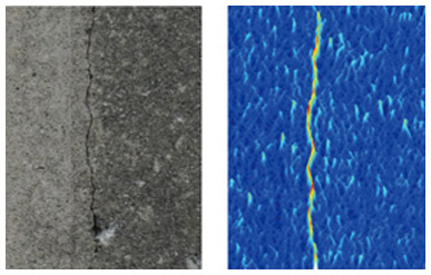
4. Crack detection algorithmAfter obstacle removal, cracks are extracted from the concrete surface areas of the image. This algorithm applies a method that emulates human neural circuitry with a neural network. The areas of concrete surface in the image after obstacle removal are partitioned into small rectangles, and a search for cracks is performed. The crack edge features are extracted, and cracks are detected by the neural network. With this algorithm, we emulate the mechanism with which we see objects with our eyes, and implement a crack line detection function that works in exactly the same way as the human eye and brain do. An original crack image and the extracted edge feature are shown in Fig. 7. The crack image is 300 × 300 pixels and the edge filter is 26 × 18 pixels.
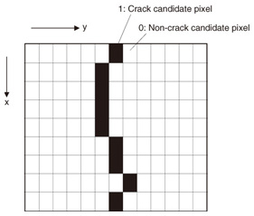
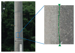
Next, the neural network extracts the crack shape from the obtained edge feature. As shown in Fig. 8, the problem is represented as a two-dimensional array of neurons that is the same size as the edge image, and the neural network searches for edges that conform to the crack shape. The specific method of using the neural network to construct the expression of behavior is described in Ref. [2]. In the crack detection results (Fig. 9), the neurons (green pixels) are seen to correspond to the crack.
5. Concluding remarksNTT Group companies are going to apply the crack detection technique described here to concrete pole inspection, and the technique is expected to play a useful role in the maintenance and management of safe facilities. Furthermore, NTT manages many concrete structures that require periodic inspection besides concrete poles, so we would like to improve this technique to enable it to meet the crack inspection needs of other structures. References
|
||||||||||||