 |
|||||||||||||||||||||||||||||||||
|
|
|||||||||||||||||||||||||||||||||
|
Regular Articles Vol. 10, No. 8, pp. 29–35, Aug. 2012. https://doi.org/10.53829/ntr201208ra1 Leveraging Semantic Web Technologies for Enterprise Information IntegrationAbstractWe describe a data-oriented architecture for exploiting integrated enterprise data as knowledge by using Semantic Web technologies. It features an extensible schema design for storing integrated enterprise data including historical data. This architecture will meet the rising demand for enterprise data integration, which is currently difficult because enterprise information is stored in different formats or has different meanings in different systems.
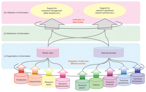
1. IntroductionIn companies, different departments and divisions operate their own information systems. Each system obtains various information (also interchangeably called data in this field) in a suitable format, so it is difficult for systems to use data in other systems. However, the demand for enterprise information integration is increasing because it is useful for business intelligence, which supports better business decision-making. Moreover, the resource description framework (RDF) [1], which expresses the relationship between things in three sentence parts—subject, object, and predicate—is becoming widely used. There are several methods [2], [3] of converting data in a relational database (RDB) into RDF format. Enterprise information is often stored in an RDB, so its conversion into machine-readable RDF format lets us find useful relations among it with the help of Semantic Web technologies. In this article, we describe a data-oriented architecture for using integrated enterprise information in RDF format. 2. Enterprise information integrationAttention is being paid to technologies such as Enterprise Search for searching enterprise data and websites [4], enterprise application integration for integrating information systems [5], and knowledge management and business intelligence for searching and analyzing enterprise information for decision-making purposes [6]. To meet these needs, enterprise information integration is crucial. However, information systems and their data schemas change over time, and these changes make it difficult to integrate enterprise data. Moreover, we need to integrate different enterprise data for different purposes, and such integrations are expensive. To manage enterprise data from different information systems and reuse it, we require a data sharing platform that does not need to modify the original data. This is the target of the study reported in this article. Enterprise data integration enables desired information stored on different systems to be obtained in an integrated manner. Moreover, it might lead to new knowledge that we could not find when the information is used separately. 3. Data sharing platform based on data-oriented architectureTo tackle the problem mentioned in section 2, we have studied a data sharing platform based on a data-oriented architecture. The aim of this architecture is to organize integrated enterprise data in order to promote effective use of it. As shown in Fig. 1, a data-oriented architecture consists of three layers: (i) organization of information, (ii) distribution of information, and (iii) utilization of information. We define these layers as follows: (i) The organization of information layer (OI layer) makes data available. (ii) The distribution of information layer (DI layer) supplies information in an expected way. (iii) The utilization of information layer (UI layer) supports the extraction of knowledge.
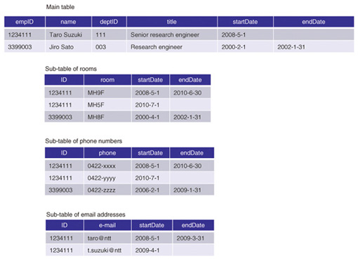
Why introduce two different layers for information retrieval? The OI layer is intended to store all of the data including historical data with timestamps while the DI layer is intended to deliver desired data by processing and editing data from the OI layer. In addition, just like services in the service oriented architecture (SOA), we treat data/information as a unit of common use across different systems. This architecture does not contradict the SOA [7]. All the data used in services in SOA is managed in an integrated fashion in the OI layer as master data. Each service accesses this master data via the data bus in the DI layer on the basis of metadata that indicates access histories, data meaning, and so on. In sections 3.1 and 3.2, we discuss the mechanisms of the OI and DI layers. In section 3.3, we present an example of a service based on this architecture. 3.1 Organization of informationThe OI layer needs to manage all data, including historical data, and changes in the data structure. To make this possible, we categorize enterprise data according to its characteristics and define guidelines for the data schema for each category. 3.1.1 Categories and characteristics of enterprise dataThere are five categories of enterprise data according to [8]: (1) master data, (2) operational data, (3) unstructured data, (4) analytical data, and (5) metadata. Master data represents essential business entities and is used in many different information services. Operational data has two types: transactions and inventory. Both are generated in the daily operations of a business, but the former is normally described as an add operation while the latter is described as an update operation [9]. Typical examples of unstructured data are text data, portable document format files (PDFs) and other documents, and data for websites. Analytical data and metadata is derived from the other types of data and is highly reusable. In this article, we focus on master data, the core data in business. Master data in our laboratory is employees, departments, research topics, and re- search achievements. Operational data associated with this master data is research papers, patents, research products, technical assistance, and technical disclosures. 3.1.2 Master data with historical dataEach information service has its own dialect. Integrating data in different information services requires some data processing such as merging data with the same meaning and eliminating inconsistencies. A typical master data management (MDM) [10] method for integrating data at a point adds a unique identifier (ID) (primary key (PK)) to each record and uses this PK as a reference from records of other tables. Data in one system might have been consistent with data in other systems at some point in the history (but may not be now); however, historical data is deleted if it is not used. Changes to data schemas and a lack of historical data make it difficult to integrate enterprise information. 3.1.3 Master data schema designWe describe a master data schema for integrated master data, including historical data. In addition to the requirements of MDM, this schema should: (1) manage historical data in a simple manner and (2) handle schema changes such as attribute addition and deletion easily. Historical data can be managed by storing all of the data either periodically or when any changes occur. The drawbacks of this method are storing redundant data and needing to have extra free space for attributes that might be added in the future. We classify attributes into two types—(1) ones that are necessary to identify a particular instance of each entity and (2) the rest—and store them separately: attributes in category (1) are stored in a main table and those in category (2) are stored in separate sub-tables (one sub-table for each attribute) [11]. In this way, when attribute values have changed, we only need to add a record to the sub-tables; and when an attribute is added or changed, we only need to create a new sub-table and do not need to change the main table. Here, we give an example of employees’ master data. It is possible to treat only the employee ID as the main attribute, but attributes such as department ID and title also need to be treated as main attributes to identify a particular employee with his or her associated time. Therefore, we decided to manage employee ID, department ID, and job title in the main table and all the other attributes such as telephone number, fax number, and email address in its corresponding sub-tables. An example of a master table of employees with historical data is shown in Fig. 2, which shows the main table and other sub-tables with PKs of the main table for reference. The main table consists of ID as a PK, the expiry date of each record (start and end dates), and the values of other attributes needed to identify a particular record. In the main table, we also include attributes that will not change before the ID expiry dates. Each sub-table contains ID (a PK of the main table), the value of the corresponding attribute, and its expiry date (start and end dates).
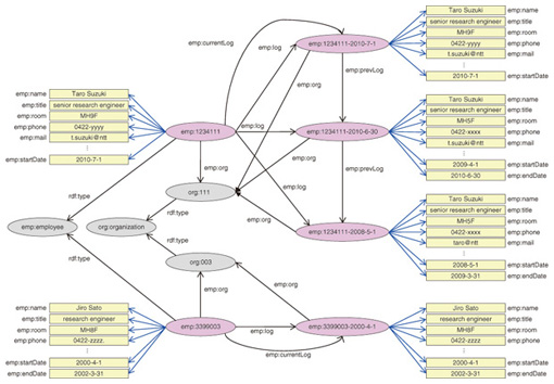
To update the value of an attribute, one must change the end date of its previous record and add a new record of a new value and a new expiry date. Since sub-tables exist for each attribute other than the ones in the main table, a new attribute could be added to the master data by just adding a new sub-table, and an attribute could be deleted by just changing the end date values of the corresponding sub-table if necessary. Therefore, this master data schema will make it possible to handle attribute changes with historical data easily. 3.2 Distribution of information3.2.1 BackgroundThe DI layer processes and edits data from the OI layer to provide desired data to the UI layer in a desired format. As mentioned in section 2, the UI layer should be able to retrieve data without knowing its structure in the OI layer. Therefore, the requirements of the DI layer are as follows: (1) hide the data structure in the OI layer from the UI layer (2) reach the desired data easily (3) retrieve the attributes of an entity easily. We convert data in the RDB to the RDF format, which is free from the RDB schema. RDF is a metadata data model defined by the World Wide Web Consortium (W3C), and one possible query language for RDF, is SPARQL [12], which is also defined by W3C. When we use RDF, naming the uniform resource identifier (URI) is a known problem like choosing the proper vocabulary. However, we do not have to worry about this problem because the data in the OI layer always has unique IDs, which can be used as URIs. Using RDF changes the second and third requirements above into: (2') express attributes of an entity simply (3') express relations between entities simply We discuss how to fulfill these requirements in section 3.2.2 and show an example of the utilization of information in section 3.3. 3.2.2 Information model for distributionIt is easy to express an RDB schema that changes over time (i.e., through column addition and deletion) in RDF format because properties in RDF format represent columns (attributes) in an RDB [13]. By using the RDF format, we aim to represent changes in RDB schemas as simply as possible. To do so, we define both columns (attributes) and relationships between tables in an RDB as properties between resources in RDF format, and the only information that we disclose to users is the properties to represent the relationship between tables. In this way, we can represent RDB schemas using properties of each resources even if RDB schemas have been changed. An example of data in RDF format that is equivalent to the RDB data in Fig. 2 is shown in Fig. 3. In our model, we define our own vocabulary because it is for enterprise use. The properties representing relationships between tables in the RDB include emp:org, emp:log, emp:currentLog, and emp:prevLog, and the other properties representing RDB columns include emp:name, emp:title, emp:room, emp:phone, and emp:mail. Regardless of changes in the RDB schemas with time, the resources connected with emp:log, emp:currentLog, or emp:prevLog properties maintain their RDB schemas at that point and have an expiry date as a property.
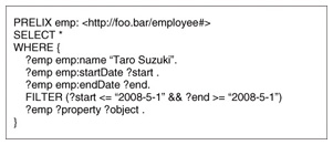
The three abovementioned requirements ((1), (2'), and (3')) are fulfilled through the introduction of a simple hierarchical expression like this. For example, a query for selecting all attributes of a particular employee at a given point in time is as simple as the one in Fig. 4.
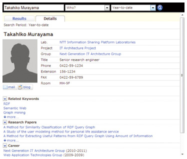
3.3 Utilization of informationAs knowledge management services, there are some services like ResearchMap [14] which allow researchers to introduce their skills and research outcomes in a cross-sectional manner. However, using knowledge management services in the style of a social network system (SNS) in companies is usually problematic. Motivating employees to update their profiles is as difficult as searching for and comparing information objectively. Therefore, we developed a way to find employees with a specified condition objectively by using integrated enterprise data. A screen image of our KnowWho service is shown in Fig. 5.
All the data in the screen image in Fig. 5 was retrieved from the DI layer by using the SPARQL endpoint. In Fig. 5, the employee’s master data shown at the top resulted from a query that searched for an entity using a given employee’s name as a search keyword, and retrieved its properties to represent attributes and their values. Similarly, KnowWho retrieved related keywords––search entities for a given employee’s name and their values of the keyword property. In order to retrieve research pa- pers, KnowWho searches research paper entities using a given employee’s name. Only the paper titles are shown in Fig. 5, but it is possible to show other related information about the research papers as well. The historical data can be retrieved by searching for entities using a given employee’s name, tracing emp:prevLog properties, and getting the values by using emp:org properties. By using a simple hierarchical model, such as the one described in section 3.2, we can establish services without knowing the RDB schema. Changing the RDB schema over time causes conditional branching in search operations. Therefore, search operations are simpler when data is in RDF format, which can represent RDB columns as properties. 4. ConclusionIn this article, we described a data-oriented architecture for using integrated enterprise data. This architecture lets us retrieve all necessary data for any purposes. We no longer need to integrate data for different purposes, so it lowers the cost significantly. We also categorized enterprise data and described a master data schema with historical data that can handle changes in schemas easily. To reuse integrated data, we introduced Semantic Web technologies to hide the original data schemas and retrieve information easily. We introduced the KnowWho service as an application of this architecture to evaluate its effectiveness. Although we focused on enterprise data in this article, RDF has endless possibilities because of its simple structure; we are planning to apply this architecture to other types of data such as linked open data [15]. References
|
|||||||||||||||||||||||||||||||||


