|
|||||||||
|
|
|||||||||
       |
Practical Field Information about Telecommunication Technologies Vol. 11, No. 4, pp. 49–56, Apr. 2013. https://doi.org/10.53829/ntr201304pf1 Failure Cases in Optical Access Facilities (Fiber Breakage in Optical Cabinets) and CountermeasuresAbstractThe Technical Assistance and Support Center undertakes detailed analyses of actual failures and proposes countermeasures to failures that occur in optical distribution facilities. This article reports two actual failure cases involving optical fiber breakage that occurred in an optical cabinet installed in multi-dwelling unit buildings and proposes countermeasures to prevent such failures in the future. This is the sixteenth in a bimonthly series on the theme of practical field information on telecommunication technologies. This month's contribution is from the Access Engineering Group, Technical Assistance and Support Center, Maintenance and Service Operations Department, Network Business Headquarters, NTT EAST.
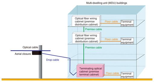
1. IntroductionThe NTT Group is constructing optical distribution facilities for providing broadband communication services to customers in Japan. Among them, the NTT Group pays a great deal of attention to customers living in multi-dwelling unit (MDU) buildings such as apartment buildings and condominiums. There is a real need to construct optical distribution facilities with optical fiber cables and optical cabinets in MDU buildings. The optical cabinets are used for terminating and connecting these optical cables. There are two kinds of optical cabinets installed in MDU buildings. The optical distribution structure in an MDU building is shown in Fig. 1. One type of cabinet is used for terminating purposes; its role is to terminate a drop cable and connect it to optical distribution facilities on the premises. The other type is used for connecting purposes; its role is to connect premise cable to floor cables.
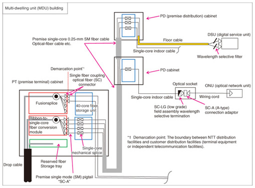
We have already reported actual failure cases and proposed countermeasures for optical access facilities [1]–[3]. Here, we report two examples of actual failure cases that have occurred with optical cabinets installed in MDU buildings, and we propose countermeasures to prevent such failures. 2. Optical cabinetsThe optical distribution configuration in an MDU building is shown in Fig. 2. The optical cabinets have a number of roles. One primary role is to serve as a premise terminal cabinet (PT cabinet). Another is to serve as a premise distribution cabinet (PD cabinet). The details of these cabinets are described in the following subsections.
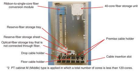
2.1 PT cabinetA PT cabinet is shown in Fig. 3. The PT cabinet has important functions, which are to terminate drop cables and to serve as a connection point for premise cables and floor cables. In addition, the PT cabinet has a demarcation-point function with SC-connectors.
2.2 PD cabinetA PD cabinet is shown in Fig. 4. The PD cabinet also has an important function, which is to serve as a connection point for premise cables and floor cables. PD cabinets have no demarcation-point function.
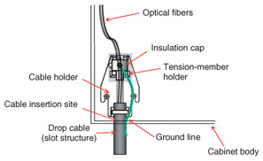
3. Cable installation3.1 Installation of a drop cableA drop cable holder used in a PT cabinet is shown in Fig. 5. When a drop cable with a slot structure is installed in a PT cabinet, a cable tension member is held by the cable holder.
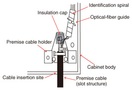
3.2 Installation of a premise cableA premise optical cable holder used in PT and PD cabinets is shown in Fig. 6. The premise cable with a cable jacket is held by the premise cable holder.
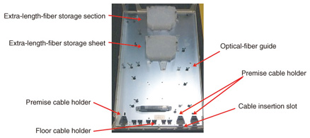
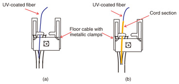
3.3 Installation of floor cablesA floor cable holder used in PT and PD cabinets is shown in Fig. 7. The floor cable holder with metallic clamps is used to install single-core indoor cables in PT and PD cabinets. An example of how ultraviolet (UV)-coated fiber is wired is shown in Fig. 8. The UV-coated fiber is passed through optical-fiber guides.
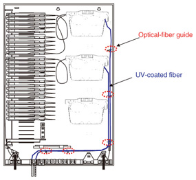
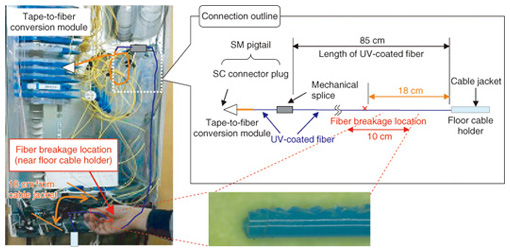
Only the UV-coated fibers in the floor cables are passed through optical-fiber guides from the floor-cable holder. This is to reduce the failure of fiber breakage, which could occur if both the optical cords and the UV-coated fibers were fastened by optical-fiber guides. However, failures can still occur. In the next section, we report two examples of actual failure cases that have occurred in optical cabinets installed in MDU buildings. We also explain the countermeasures that were applied. 4. Failure case and countermeasure I4.1 BackgroundA fiber breakage of an optical fiber occurred near a floor cable holder in a PT cabinet, as shown in Fig. 9.
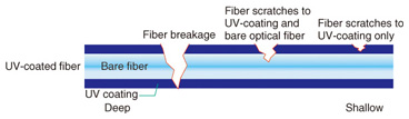
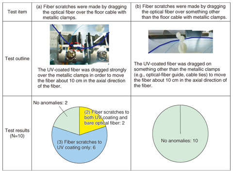
The fiber breakage occurred 18 cm away from the end of the cable jacket holding a single-core floor cable. We also found many scratches on the fiber that extended about 10 cm from the fiber breakage. The length of the UV-coated fiber measured from the edge of the cable jacket is generally required to be more than 160 cm. In this case, the length was less than 85 cm. Therefore, the UV-coated fiber could not be stored inside the 40-core fiber storage unit because it was too short. 4.2 Reproduction experimentWe inferred the cause for the fiber breakage and carried out experiments to reproduce the failure (Fig. 10). We measured the extent of the damage of the fiber scratches on a three-level basis (1: fiber breakage, 2: fiber scratches affecting both the UV-coating and bare optical fiber, 3: fiber scratches on the UV coating only). The results of the experiment are listed in Table 1.
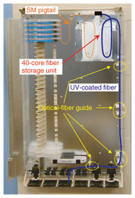
(a) Fiber scratches caused by dragging the optical fiber over a floor cable with metallic clamps The UV-coated fiber was pushed strongly against a floor cable with metallic clamps. Then, the UV-coated fiber was dragged over the floor cable with metallic clamps so that the UV-coated fiber moved about 10 cm in the axial direction of the fiber. The result of this action was that a fiber breakage (fault 1) occurred 0 out of 10 times, fiber scratches to both the UV-coated fiber and the bare fiber (fault 2) occurred 2 out of 10 times, and fiber scratches to only the UV coating (fault 3) occurred 6 out of 10 times. (b) Fiber scratching caused by dragging the optical fiber on something other than floor cable with metallic clamps We found that none of the faults occurred in this reproduction experiment. 4.3 Cause of failure and countermeasureWe considered the reason for the fiber breakage. The optical fiber guides failed to hold the UV-coated fiber. In addition, the UV-coated fiber was scratched when it was dragged over the floor cable with the metallic clamp. We also considered that the scratches on the fiber would become larger over time. This would eventually lead to fiber breakage. A countermeasure to this problem is to ensure that the UV-coated fiber is passed appropriately through the optical-fiber guides. It is also essential to have a sufficient length of the UV-coated fiber wires and to use the correct placement methods in the optical cabinets. For these reasons, the length of fiber that is needed should be roughly estimated before the actual wiring of the UV-coated fiber is done. In addition, it is recommended that the extra length of the UV-coated fiber be adjusted in order to prevent sagging of the optical fiber in the 40-core fiber storage unit (Fig. 11).
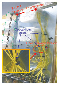
5. Failure case and countermeasure II5.1 BackgroundThe fiber breakage occurred after carrying out work to install the wiring in a PD cabinet. The wiring conditions and fiber breakage location in the PD cabinet are shown in Fig. 12.
The fiber breakage occurred near an optical-fiber guide. As mentioned previously, only UV-coated fiber should be held by the optical-fiber guides. In this case, both the UV-coated fibers and optical cords were being held by the optical-fiber guides. 5.2 Reproduction experimentConsidering the fiber breakage location, we inferred the fiber breakage causes (a) and (b). Therefore, we carried out an experiment to reproduce the three levels of fiber scratches shown in Fig. 10. The results of the experiment are listed in Table 2.
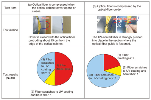
(a) Optical fiber gets compressed when closing the optical cabinet We considered the possibility that a fiber breakage could occur if the UV-coated fiber was compressed when a cabinet cover was opened or closed. We carried out an experiment to open and close the cabinet cover when the UV-coated fiber was protruding about 15 cm from the edge of the cabinet. The results indicated that a fiber breakage (fault 1) occurred 5 out of 10 times, fiber scratches to both the UV coating and bare fiber (fault 2) occurred 1 out of 10 times, and fiber scratches to only the UV coating (fault 3) occurred 4 out of 10 times. (b) Optical fiber gets compressed during fastening of optical-fiber guide We also considered the possibility that if both optical cords and UV-coated fibers were fastened by the optical-fiber guides, a fiber breakage could occur in the UV-coated fiber. Therefore, we tried strongly pushing the UV-coated fiber into place in order to fasten it with the optical-fiber guide. The results revealed that a fiber breakage (fault 1) occurred 2 out of 10 times, fiber scratches to both the UV coating and bare fiber (fault 2) occurred 1 out of 10 times, and fiber scratches to only the UV coating (fault 3) occurred 7 out of 10 times. 5.3 Cause of failure and countermeasuresThe results of the reproductive experiments reinforced our view that there were two key reasons for fiber breakages occurring in optical cabinets. One was that a fiber breakage could occur if the UV-coated fiber was compressed when the cabinet cover was opened or closed. The second was that a fiber breakage could occur if both optical cords and the UV-coated fiber were fastened by the optical-fiber guide. Consequently, strongly bending a fiber at a sharp angle, as has been done in the past, could lead to fiber breakage in optical cabinets. A countermeasure to this problem is to take special care when opening and closing the cabinet. In addition, it is also essential that only the UV-coated fiber, and not the optical cords, be fastened by the optical-fiber guides. 6. ConclusionThis article reported two actual failure cases and proposed countermeasures for failures that occurred in optical cabinets installed in MDU buildings. The key points are as follows. (1) It is recommended that the necessary length of fiber be roughly estimated before actually wiring the UV-coated fiber. In addition, any extra length of the UV-coated fiber should be adjusted to prevent sagging of the optical fiber inside the optical cabinets. (2) It is important to take care when opening and closing the cabinet cover. It is also essential to fasten only UV-coated fiber with the optical-fiber guides, and not to fasten the optical cords. References
|
||||||||