|
|||||||||
|
|
|||||||||
       |
Regular Articles Vol. 11, No. 10, pp. 27–32, Oct. 2013. https://doi.org/10.53829/ntr201310ra2 Reducing Electric Power Consumption for Air Conditioning by Improving Temperature Distribution in Telecom Equipment RoomsAbstractThis article presents the results of an electric-power-reduction experiment that was conducted in collaboration with the NTT WEST Kochi branch. One effective way to reduce the amount of electric power required for air conditioning in a telecom equipment room (TER) is to eliminate hot spots. In the experiment, the causes of two hot spots generated in the existing TER were analyzed, and various heat-control methods were implemented to eliminate them. Then the effects these methods had on reducing the temperature and on reducing the required air conditioning power were evaluated. Keywords: telecom equipment room, air conditioning, electric power reduction
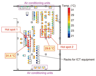
1. IntroductionThe suspension of nuclear power plant operations after the catastrophic disaster in northeastern Japan in March 2011 caused an electric power shortage during the subsequent summer and winter in Japan. It has also led to an increase in the price of electric power. The NTT Group consumes 8 billion kWh of electricity per year (corresponding to 1% of gross electric power consumption in Japan) in order to provide its telecommunication services. Consequently, any reduction in the power supply is an extremely important issue from the viewpoint of corporate social responsibility and business continuity. The NTT group has therefore been implementing various measures to remedy this situation. One of these measures involves reducing the amount of power required for air conditioning in telecommunication equipment rooms (TERs). TERs are found in NTT buildings throughout Japan and contain various kinds of information and communications technology (ICT) equipment such as routers and servers, as well as the power supply units and air conditioning units required by them. Most TERs utilize a raised-floor system so that cold air from the air conditioning units can circulate throughout the floor space in order to cool the ICT equipment. The hot exhaust from the ICT equipment is then returned to the air conditioning units located near the ceiling. However, in many TERs, a variety of factors may result in the formation of hot spots, where the temperature is higher than in other parts of the room. In this situation, the air conditioning outputs have to be set higher in order to prevent failure of the ICT equipment. However, this also causes an increase in electric power consumption. If such hot spots can be eliminated, the power consumption could be reduced by lowering the air conditioning output. NTT Energy and Environment Systems Laboratories has been researching various methods to cope with these sorts of heat problems in TERs [1]–[3]. This article presents the results of a power-reduction experiment that was conducted in collaboration with the NTT WEST Kochi branch. In this experiment, various methods to control heat were implemented and compared. As a result, air conditioning power-reduction effects were achieved in conjunction with reductions in hot spots. 2. Visualization of TER in NTT Kochi-Naka buildingThe TER in the NTT Kochi-Naka building where the experiment was conducted covers an area of 430 m2 and contains 100 racks for ICT equipment and seven air conditioning units. It also houses the power and temperature visualization system that NTT Energy and Environment Systems Laboratories developed and installed. This system monitors the value of electric power that each piece of ICT equipment consumes and the temperature around it, and displays the data as a two-dimensional distribution map or time-domain graph. The sensors that record the data are installed in each rack and air conditioning unit. The temperature distribution map for the entire room is shown in Fig. 1. The color of each balloon in the figure signifies the temperature at that point. As shown in the figure, there were originally two hot spots in the room. One (hot spot 1) was found near the center of the room on the left-hand side, where the maximum temperature recorded was 31.4°C. The other (hot spot 2) was located near the center on the right-hand side, and the maximum temperature recorded there was 29.6°C.
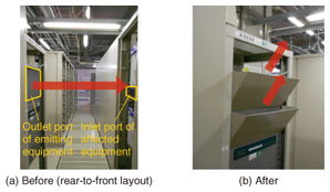
We investigated the causes of the elevated temperatures at these two hot spots, introduced some modifications in an attempt to overcome the overheating problem, and evaluated the effectiveness of these solutions. We carried out this work with the cooperation of the NTT WEST Kochi branch, NTT WEST-SHIKOKU, NTT NEOMEIT Shikoku branch, and NTT FACILITIES KANSAI. 3. Solutions for hot spots in TERs3.1 Solution 1: Airflow control panelsOur investigations revealed that hot spot 1 had two causes. One was the rear-to-front layout in which the exhaust port of one ICT unit faces the intake port of another. As a result, the high-temperature exhaust from the ICT equipment (emitter equipment) flows directly into the intake port of adjacent units (affected equipment), thereby raising the intake temperature (Fig. 2(a)). To avoid this situation, ICT equipment has in recent years been arranged to form a cold aisle (hot aisle) across which intake ports (exhaust ports) face each other when new TERs are constructed. However, in TERs that were constructed before this arrangement was introduced and that are still in operation today, the rear-to-front layout is still common. To improve this state of affairs, we added airflow control panels to the exhaust port of the emitter equipment, so that the exhaust was now directed upwards (Fig. 2(b)). As a result, the direct effect of the high-temperature exhaust on the affected equipment was eliminated without needing to alter their actual layout. The shape of the panel was designed with the help of airflow computer simulations so that other equipment nearby would not be affected.
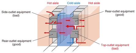
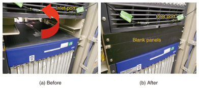
3.2 Solution 2: Blank panelsThe other cause of elevated temperatures at hot spot 1 was the hot air exhaust emitted from the top face of the equipment. When ICT equipment has an exhaust port on its top face, bottom face, right side or left side, the exhaust from that port enters the cold aisle as well as the hot aisle and raises the temperature (Fig. 3).
To correct this, we installed blank panels so that the hot exhaust only flowed into the hot aisle (Fig. 4).
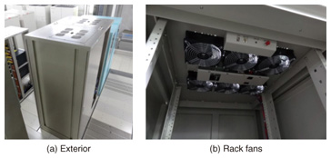
3.3 Solution 3: Adjustment of air quantity taken in by forced-air cooling racksWhile investigating hot spot 2, we found that the circulation of cold air under the raised floor was inadequate in that area. One of the reasons for this was suspected to be excessive cooling of the forced-air cooling racks, 30 of which were installed in that particular room. A forced-air cooling rack is a type of closed rack that takes in cold air from under the raised floor using fans, and then uses this cold air to cool the ICT equipment (Fig. 5). It is often used for equipment that produces a lot of heat because it can supply large amounts of cold air for cooling purposes. Generally, the quantity of air that the rack takes in is set in the design phase and is not changed after that. As a result, the quantity of air that the rack takes in may be considerably larger than the amount of cooling the equipment in the rack actually requires. Massive overconsumption by a number of racks may, therefore, cause a lack of cold air under the raised floor.
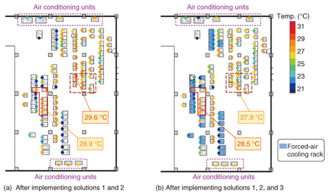
We adjusted the quantity of air taken in by the racks so that the inside temperature was maintained at the optimum level. This was achieved by measuring the temperature of the exhaust from the upper surface of each rack and then minimizing the number of fans running so that the temperature of the exhaust did not exceed the steady-state value determined in advance. 4. Some solutions to optimize temperature and prevent hot spotsThe temperature distribution throughout the room after introducing the airflow control panels and the blank panels is shown in Fig. 6(a). A comparison of the results with the image in Fig. 1, which shows the temperature distribution before alteration, shows that the temperature at hot spot 1 was significantly reduced. The maximum temperature fell from 31.4°C to 28.9°C. By contrast, the temperature at hot spot 2 did not change significantly. This is because the solutions implemented only have a localized effect. The temperature distribution after adjusting the quantity of air taken in by the forced-air cooling racks, in addition to the two solutions implemented earlier, is shown in Fig. 6(b). Comparing Fig. 6(a) with Fig. 6(b) shows that the temperature of most of the racks (except the forced-air cooling racks) was reduced as a result. The maximum temperature of hot spot 2 fell from 29.6°C to 27.9°C, and that of hot spot 1 dropped to 28.5°C.
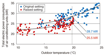
5. Electric power savings achieved by reducing air conditioningAdopting the three solutions described above reduced the maximum temperature of the room to 28.5°C. This meant that it was now possible to reduce the amount of air conditioning needed, so we altered the settings of all the air conditioning units and observed the change in electric power consumption. The temperature setting for the return air entering the air conditioning units was raised by 1.5°C in order to raise the maximum temperature of the room to 30°C (the usual temperature maintained in TERs). The relationship between the total amount of electricity used by all the air conditioning units in the room and the outdoor temperature is shown in Fig. 7. The blue and red points show the power consumption levels measured when the room temperature was at its original setting and at the raised setting, respectively. Air conditioning power consumption decreased by 3.2 kW (11%) after raising the temperature setting by 1.5°C (at an outdoor temperature of 20°C). This means that the cost of air conditioning could be reduced by 300,000–400,000 yen every year.
6. ConclusionAs a result of this joint experiment carried out in conjunction with the NTT WEST Kochi branch, the status of hot spots in the TER inside the Kochi-Naka building was improved significantly, and the air conditioning requirements were reduced. Changing the temperature settings by 1.5°C achieved an 11% reduction in air conditioning power consumption when the outdoor temperature was 20°C. We are continuing to research and improve these power-saving techniques so that they can be adopted more widely, in cooperation with each company within the NTT Group. References
|
||||||||