|
|||||||||||||||||
|
|
|||||||||||||||||
       |
Regular Articles Vol. 11, No. 11, pp. 39–44, Nov. 2013. https://doi.org/10.53829/ntr201311ra1 Fiber-mounted Electro-optic Probe for Microwave Electric-field Measurement in Plasma EnvironmentAbstractThe demand for greater precision in electric-field measurements is increasing. To meet this demand, NTT Microsystem Integration Laboratories has developed an electro-optic (EO) probe that is mounted on the tip of an optical fiber and has no metal components. This article describes the basic principles and improvements in sensitivity stability and thermal and magnetic resistance of the EO probe. It also presents the results of microwave electric-field measurements conducted in an electron cyclotron resonance ion engine installed on an asteroid explorer under the collaboration of NTT and the Japan Aerospace Exploration Agency. Keywords: electro-optic (EO) probe, optical fiber, plasma environment
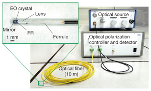
1. IntroductionElectric-field sensors are widely used to measure various kinds of electromagnetic fields such as weak ones existing naturally in the environment and artificial ones generated by high-power microwaves. Measurement of these fields usually disturbs the radiated electromagnetic waves. Conventional electric-field sensors contain metal components that can increase these disturbances, and are approximately as large as a wavelength that can determine a spatial resolution which is an inherent problem when attempting to precisely measure the desired electric field. To overcome this issue, at NTT Microsystem Integration Laboratories, we have developed an electro-optic (EO) probe that employs an optical fiber typically used in optical communications [1], [2]. The EO probe was designed based on the Pockels effect and contains no metal; thus, it can reduce the disturbances in the electromagnetic field that occur during measurement. Moreover, the size of the EO probe is small and can be determined based on the optical beam propagating in an EO crystal. Moreover, the Japan Aerospace Exploration Agency (JAXA) has been researching and developing an electron cyclotron resonance (ECR) ion engine that can be installed in an asteroid explorer and has also improved its propulsion performance [3], [4]. To improve the performance, JAXA needed to be able to measure the microwave electric-field distribution of the internal plasma in the ion engine during actual operation. However, conventional electric-field sensors cause disturbances such as scattering of the electric field, which makes it necessary to modify the structure of the ion engine in order to insert a probe in it. This makes it difficult to precisely diagnose internal phenomena based on microwave electric-field measurements of the accelerated plasma in the ion engine during operation. Thus, NTT Microsystem Integration Laboratories and JAXA have been collaborating in the research and development of microwave electric-field measurements in the ion engine with a focus on achieving noninvasiveness and high spatial resolution of the EO probe. The configurations and basic properties of the EO probe are described in section 2, and the improvements made to the probe are explained in section 3. The experimental setup is described in section 4, and in section 5, the results of the microwave electric-field measurements in the ion engine during actual operation are presented. 2. Fiber-mounted EO probeA photograph of the EO probe developed by NTT Microsystem Integration Laboratories for the microwave electric-field measurements is shown in Fig. 1. The EO probe employs photonic techniques based on the Pockels effect to detect the microwave electric field. It consists of a dielectric reflector, an EO crystal, a Faraday rotator (FR), a collimator lens, a ferrule, and a polarization-maintaining fiber (PMF). The reflector, EO crystal, FR, lens, and ferrule are longitudinally mounted on the tip of the PMF with optical adhesive that has a refractive index as high as that of fused quartz. The diameters of these mounted components are 1 mm, while that of the PMF is 0.256 mm, and the lengths of the EO probe and the PMF are 15 mm and 10 m, respectively. The EO crystal is zinc telluride (ZnTe) with a Pockels coefficient of around 4 pm/V at an optical wavelength of 1550 nm. A lightwave propagates through these components without any distortion at zero electric field. In this probe, the refractive index along the crystallographic axes of the EO crystal changes, and then the phase of the lightwave propagating along each axis in the EO crystal shifts in linear proportion to the intensity of the applied microwave electric field. That is, the refractive index of the EO crystal depends on the optical polarization relative to the crystal axes. ZnTe has a cubic zinc-blende lattice, and the polarization of the lightwave propagating normal to the (110) plane changes as the microwave electric field is applied to the axis normal to the (001) plane. The microwave electric field can be measured by detecting the polarization change of the lightwave propagating round-trip through the crystal in the EO probe. In Fig. 1, the measurement direction of the microwave electric field is transversal to the longitudinal one of the EO probe.
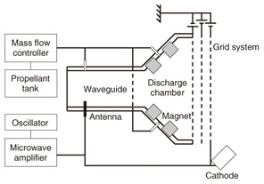
3. ECR ion engine installed in asteroid explorerA schematic diagram of the ECR ion engine that was installed in the asteroid explorer developed by JAXA is shown in Fig. 2. The ECR ion engine basically consists of a waveguide, a discharge chamber, and a three-grid system. Inside the ECR ion engine, there is a dipole antenna and a propellant inlet at one end of the waveguide. The other end of the waveguide is connected to the discharge chamber (right side in Fig. 2). The ECR ion engine uses a microwave with a frequency of 4.25 GHz to produce plasma, which is transmitted through the waveguide to the discharge chamber. The 4.25-GHz microwave and a propellant, xenon (Xe), are injected from the waveguide and travel to the discharge chamber. In the discharge chamber, Xe electrons are continuously accelerated by the ECR heating of the microwave and the mirror magnetic field generated by two rings of magnets. ECR plasma is formed through subsequent electron-neutral and electron-ion collisions. JAXA has improved the thrust force of the ECR ion engine by changing the way the propellant is injected [3], [4]. In conventional ECR ion engines, the propellant inlet is located only at the end of the waveguide. In the improved ECR ion engine, propellant inlets are added between the magnet rings in the discharge chamber.
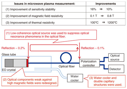
4. Improvements to EO probe for measurements in ECR ion engineAs described in the previous section, the environment inside the ECR ion engine is very severe, and thus, the EO probe needed to be modified to improve its performance in carrying out the specified measurements in the ECR ion engine during actual operation, as shown in Fig. 3.
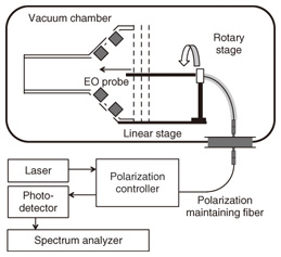
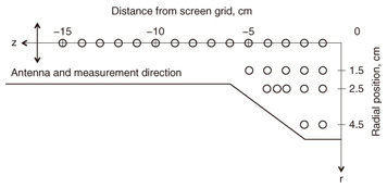
(1) To achieve stable measurement with less fluctuation than that of a microwave oscillator output, a low coherence optical source was used to suppress the optical resonance phenomena in the optical fiber. Accordingly, the sensitivity fluctuations of the fiber-optic EO probe were reduced from 16% to less than 10%. (2) To enable the EO probe to be applied to high-magnetic-field areas in the ECR ion engine, the optical components that were weak against high magnetic fields were redesigned. This increased the magnetic-field resistance from 0.1 T to over 0.8 T. (3) To enable application of the EO probe to high temperature areas, a water cooling system with a double capillary structure was introduced [5]. The outer diameter of the capillary structure is 3 mm, which made it possible to insert it into the ECR ion engine through the grids without requiring any additional perforations or modifications. 5. Measurement setupThe experimental setup [6] used to conduct the electric-field measurements inside the ECR ion engine is shown in Fig. 4. In the vacuum chamber, the EO probe is placed in a silica glass tube 3 mm in diameter, which is mounted on a linear stage and a rotary stage positioned by stepping motors. The probe is remotely inserted in the discharge chamber through the center aperture of the grids. The measurement interval is 1 cm. The rotational angle is adjusted so that the measurement direction of the EO probe is parallel to the longitudinal direction of the dipole antenna, where the maximum electric field is detected. The input microwave power is 34 W.
A laser diode (LD), polarization controller, photodetector (PD), and spectrum analyzer are set outside the vacuum chamber. The polarization controller comprises a polarizer, a circulator, half and quarter-wave plates, and an analyzer. The lightwave emitted from the LD is polarized linearly by the polarizer and input into the PMF; it reaches the tip of the probe through the circulator. The lightwave makes a round-trip pass through the EO crystal via reflection by the dielectric reflector, and the polarization of the lightwave changes in proportion to the microwave electric field along the measurement direction. The polarization-changed light is returned to the polarization controller and converted to linearly polarized light by the analyzer. That is, the lightwave is intensity-modulated by the microwave electric field. The intensity-modulated light is detected and converted to an electric signal by the PD. The amplitude and phase of the electric signal are proportional to those of the microwave electric field, and the frequency of the electric signal is the same as that of the microwave electric field. As a microwave signal is input into the ion thruster at a frequency of 4.25 GHz, the spectrum analyzer displays the spectrum with the intensity proportional to that of the measured microwave electric field at a frequency of 4.25 GHz. Prior to the measurement, the probe is calibrated using a rectangular waveguide with a cross section of 2.0 × 4.0 cm2 in atmospheric pressure. The calibration results agreed well with the theoretical electric-field intensity in the waveguide at a known microwave power. In the measurement, the EO probe was kept at 25°C by a cooling system under beam acceleration in order to achieve the same accuracy as the calibration. The measurement was conducted at various points inside the thruster, as shown in Fig. 5.
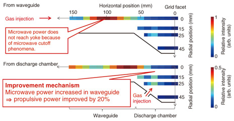
6. Electric-field measurement [7]The intensity distribution of a microwave electric field parallel to the dipole antenna in the ECR ion engine is shown in Fig. 6. The measurement was conducted with respect to the propellant inlet positions of the waveguide and the discharge chamber at a flow rate of 2 sccm under beam acceleration. Each graph has a different scale of intensity to express the differences in the intensity of the electric field between the center axis and the ECR region.
As shown in the figure, the intensity distribution of the electric field with plasma is completely different between the propellant inlet positions. From the waveguide inlet, the highest value was recorded at 100 mm from a grid facet. By contrast, from the discharge chamber inlets, the highest value is located more downstream. Moreover, the absolute value of the propellant injection from the discharge chamber inlets is half of that from the waveguide inlet. This phenomenon resulted in the saturation of beam current at 2 sccm from the waveguide inlet. The highest intensities exist at over 12,000 V/m around 100 mm from the grid facet. At that point, the intensities of the ECR region are quite low. Hence, it is highly possible that insufficient microwave power is supplied to the ECR region, which results in the reduction of the beam current. This measurement revealed that the difference in the low-beam current mode and the high-beam current mode corresponds to the presence of the peak of the electric-field intensity of the microwave in the waveguide. This peak is possibly suppressed by changing the way the propellant is injected from the waveguide inlet to the discharge chamber inlets. This result indicates that the tendency is the same as that in the laser absorption spectroscopy of Xe I 828.01 nm [4], which can explain the mechanism of improvement of the propellant force in the ECR ion engine. 7. Future tasksWe are now considering the operability of the optical components in the probe because of their complicated design structure and the long-term reliability of the optical adhesive resin used to fix the optical components such as the EO crystal and the optical fiber. NTT Microsystem Integration Laboratories aims to improve the operability by using a novel structure for the fiber-mounted EO probe and to increase the probe’s reliability by improving the optical adhesive resin. The last step will be to finalize the design of the fiber-mounted EO probe used for obtaining microwave electric-field measurements within the microwave discharge ion engine. References
|
||||||||||||||||