|
|||||||
|
|
|||||||
       |
Practical Field Information about Telecommunication Technologies Vol. 12, No. 6, pp. 61–65, June 2014. https://doi.org/10.53829/ntr201406pf1 Fault Cases and Countermeasures for Optical Fiber Cables in Optical Network FacilitiesAbstractThis article introduces case studies of failures that have occurred in optical fiber cables as well as some countermeasures against such failures. This is the twenty-third of a bimonthly series on the theme of practical field information on telecommunication technologies. This month’s contribution is from the Access Network Engineering Group, Technical Assistance and Support Center, Maintenance and Service Operations Department, NTT EAST. Keywords: optical fiber cables, access equipment, fault cases
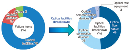
1. IntroductionThe number of FLET’S HIKARI optical fiber broadband service subscribers reached over 17.8 million as of the end of March 2014. In contrast, the number of subscribers using PSTN (Public Switched Telephone Network) consisting of metallic cables was recorded at 27 million as of the end of the same period. The Access Network Engineering Group has been investigating failures that occur in access network facilities including optical fiber cables and metallic cables. We investigated a range of failure items in 2012, as shown in Fig. 1. The figure indicates that optical fiber cable and optical connection devices account for nearly half of the total failures. We reported fault cases of field assembly connectors in optical access facilities in a previous issue (July 2011) [1]. Therefore, we report here the fault cases of optical fiber cables investigated in 2012.
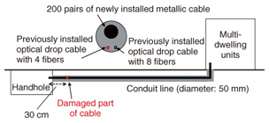
2. Fault case of damage to an optical drop cableOne case involved an optical drop cable that was damaged during the installation of a new metallic cable along a conduit line. We investigated the cause of the damage to the optical drop cable. 2.1 Overview of damageA new metallic cable was installed in the conduit line connecting a handhole to a multi-dwelling unit (Fig. 2). The installation involves first laying a rod for cables and using the rod to lay a polypropylene string. The rod is then removed, and the polypropylene string is used to install a metallic cable. Finally, the polypropylene string is removed.
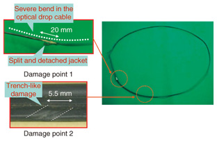
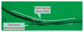
Just after the installation, we received a report about an interruption in the optical communication service provided by the previously installed optical drop cable. That cable had four fibers in the same conduit line. An investigation revealed damage to the optical drop cable in the conduit line about 30 cm from the handhole entrance. 2.2 Results of investigationThe damaged optical drop cable that was removed from the conduit line is shown in Fig. 3.
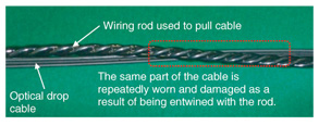
The form of the damage (damage point 1) consisted of a severe bend in the cable and a split and detached cable jacket. Another point of damage consisting of a trench (damage point 2) was located 15 cm from damage point 1. We confirmed using X-ray imaging that two optical fibers were broken at damage point 1. Moreover, we also confirmed with a video microscope that the UV (ultraviolet) coating on the broken optical fibers was stripped, leaving the bare fibers exposed. 2.3 Reproduction of cable damageWe investigated whether installation of metallic cable can damage the optical drop cable. Specifically, we entwined and tensioned a piece of optical drop cable with wiring rod, with polypropylene string, and with metallic cable, respectively, as shown in Fig. 4, in order to intentionally damage the cable. We then compared the resulting damage with the damage from the removed cable to see if the same kind of cable bend, jacket detachment, and optical fiber breakage occurred. Finally, we confirmed that the damage that occurred when the wiring rod was used most resembled that of the removed cable (Fig. 5).
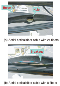
2.4 DiscussionIn our examination, we confirmed that the optical drop cable was damaged when it was pulled after being entwined with the wiring rod. Therefore, we recommended two countermeasures to prevent this damage: (i) Install a new conduit line to avoid using multiple threading cables in the same conduit, and (ii) in the inevitable case that new metallic cable is installed in the conduit line containing previously installed optical drop cable (in the manner described in this report), the metallic cable must be placed very carefully. Then the installer should check whether excessive force has been applied or whether existing cables have been moved. 3. Fault case of damage to aerial optical fiber cable caused by fireWe describe here a fault case involving the interruption of optical telecommunication service via an aerial optical fiber cable damaged by fire six years previously. 3.1 Overview of damageAfter receiving a report of a disruption of the optical telecommunication service, maintenance personnel searched for the fault location in the aerial optical network. They found a breakage in the sheath of two optical fiber cables. Upon closer inspection, they found that one optical fiber cable had bulges and a hole in the sheath, and the other cable had breakages, as shown in Fig. 6.
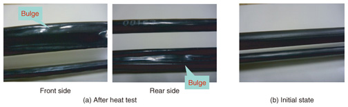
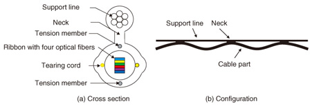
3.2 Investigation at location of the damaged optical fiber cableWe interviewed the local fire department and found that three wooden houses had been completely destroyed by fire about six years earlier in an area near the damaged optical fiber cable. The damaged cables were directly downwind of the fire when the fire occurred. 3.3 Reproduction of the damaged cableFires of the type that consumed the wooden buildings typically have temperatures exceeding 1000°C (according to a fire handbook published by Kyoritsu Shuppan Co., Ltd. in 1997). The cable sheath material generally begins to deform at temperatures over 150°C. Therefore, we heated the same type of aerial optical cable in a heater in order to replicate the deformation of the optical cable by heat. When the surface temperature of the cable exceeded 150°C, the cable sheath started to soften. After 15 minutes, the cable deformed, and after 60 minutes, it started to bulge (Fig. 7), and its shape resembled that of the piece of removed cable described in the previous section. The configuration of this type of aerial optical fiber cable with 24 fibers is shown in Fig. 8.
3.4 DiscussionFrom the results of the above investigation, we presumed that the change in the shape of the cable sheath and the support-line surface was caused by the high surface temperature, which reached about 150°C due to the heat from the fire. Moreover, as a result of the cable surface being stretched by the force of the tension member inside the optical fiber cable, the sheath starts to tear, and after many years of exposure to weather and UV light, it degrades and eventually breaks. It is difficult to confirm the state of damage to an aerial optical fiber cable after a fire by conducting only a visual inspection from the ground. Therefore, as a countermeasure, it is necessary to carry out inspections from close up using an aerial work platform. 4. Fault cases of damage to optical fiber cable by wildlifeWe introduce two fault cases of damage to optical fiber cables caused by wildlife. 4.1 Damage by arboreal mammals (such as martens and civets)The first fault case involved an optical drop cable that was cut during the night. A lot of scarring was found on the sheath of the damaged cable, and the optical fibers inside the damaged cable were completely severed. These damaged optical drop cables are shown in Fig. 9. The appearance of damage on the sheath of the optical drop cable was different from the damage caused by the wildlife we had investigated in previous cases. These fault cases happened at night, but they were in areas where there were no nocturnal bird species with beaks capable of pecking through optical drop cables. The damage was also quite different from the damage caused by the incisors of rodents such as squirrels and mice. Therefore, we presumed that the damage to the cable was caused by an arboreal mammal such as a marten or civet.
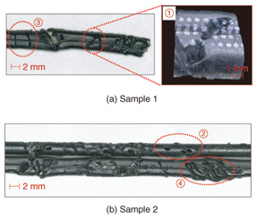
4.2 Damage due to powder-post beetles (Bostrichidae)The other fault case involved an optical drop cable that had damage with a different appearance. The damaged area was littered with small punctures that had a diameter of 1 mm. The Cryptotympana facialis (a kind of cicada) is a familiar culprit of puncture damage [2], but we had not received any reports of damage to optical drop cables due to Cryptotympana facialis in the area where this fault occurred. The traces of damage to the optical drop cable were near the center section of the cable. The punctures had a circular hole-like shape with a diameter of 1 mm and were in the notch section of the optical drop cable (Fig. 10).
We examined the punctures and found that they had an insertion angle of 90°. In contrast, a typical puncture caused by the ovipositor of Cryptotympana facialis is characterized as a stab that occurs at an insertion angle of about 30°. This difference in the insertion angle led us to conclude that the damage was not caused by Cryptotympana facialis. Moreover, we confirmed that no carcasses or eggs of these insects were found in the extracted section of the optical drop cable. We also found five semicircles 0.1 mm in diameter where the UV coating had been stripped away. The damage was similar to that caused by a bamboo powder-post beetle (Bostrichidae) examined in previous investigations. In particular, the width of the tip of the mandible of a bamboo powder-post beetle is about 0.1 mm, and the surface of the damaged sections is characterized by marks that appear to be less than or equal to 0.1 mm in size. Moreover, the damage marks on the optical drop cable had an insertion angle of 90°. In light of these facts, we inferred that the insect that inflicted the damage was Bostrichidae. 5. Concluding remarksIn this article, we reported fault cases of damage to optical fiber cables and proposed some countermeasures against such damage. The Technical Assistance and Support Center reached its 25th anniversary in 2012, and last year marked the 50th year of our technical collaborations (including those of our previous incarnation, the Technical Collaboration Department). Utilizing the knowledge and experience that we have accumulated up until the present, we will strive to continuously improve the reliability of access facilities and equipment while implementing measures to reduce malfunctions and service failures. References
|
||||||