|
|||||
|
|
|||||
       |
Practical Field Information about Telecommunication Technologies Vol. 12, No. 8, pp. 42–46, Aug. 2014. https://doi.org/10.53829/ntr201408pf1 Fault Cases in an IP Phone Circuit Accommodating a PBX via a VoIP-GWAbstractThis article introduces fault cases in an Internet protocol (IP) phone circuit accommodating a PBX (private branch exchange) via a VoIP-GW (voice over IP gateway). This is the twenty-fourth of a bimonthly series on the theme of practical field information on telecommunication technologies. This month’s contribution is from the Network Interface Engineering Group, Technical Assistance and Support Center, Maintenance and Service Operations Department, Network Business Headquarters, NTT EAST. Keywords: IP phone, PBX, VoIP-GW
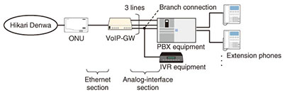
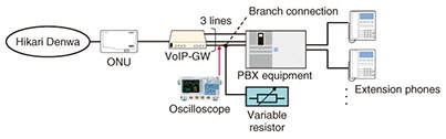
1. IntroductionThe penetration of broadband services has also reached telephone services, which has led to a migration from analog phones to Internet protocol (IP) phones. We introduce here two cases of faults occurring in a configuration that accommodates a private branch exchange (PBX) via a voice over IP gateway (VoIP-GW) in an IP phone circuit. These examples show how faults can be investigated by collecting data at various troubleshooting points, and they also demonstrate the importance of maintaining the required values stipulated in product specifications. 2. Overview of fault cases2.1 Line disconnect occurs when PBX receives an outside call2.1.1 Equipment configurationThe equipment configuration of a customer that uses NTT’s IP phone service called Hikari Denwa is shown in Fig. 1. The PBX is connected to the optical network unit (ONU) through the VoIP-GW with three analog lines. One of the lines leads to the interactive voice response (IVR) equipment as a result of branching off the path from the VoIP-GW into the PBX equipment. The VoIP-GW is also connected to an Ethernet line, and it bidirectionally converts analog signals into IP packets or IP packets into analog signals.
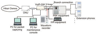
2.1.2 Fault descriptionWhen incoming calls came in from the outside, the line would sometimes disconnect before answering. This problem had been occurring since the time of analog-line use prior to introducing Hikari Denwa. 2.1.3 Inspection methodSince we could not confirm the occurrence of a line disconnect before answering in an on-site incoming-call connection test, we decided to conduct long-term monitoring and analyze the collected data. The inspection setup is shown in Fig. 2 and described below.
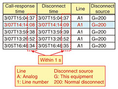
a) We used a maintenance console installed in a personal computer (PC) to collect and analyze the VoIP-GW call log. b) We used a packet capturing tool installed in a PC to capture packets in the Ethernet section between the ONU and the VoIP-GW and then analyzed the captured data. c) We used a waveform recorder to monitor signals in the analog-interface section between the VoIP-GW and the PBX equipment. 2.1.4 Inspection resultsa) The call log collected from the VoIP-GW revealed the existence of calls in which the time interval from incoming-call response to line disconnect was less than one second. It was confirmed that all of these calls were disconnected by the VoIP-GW on the call-terminating side. These results are shown in Fig. 3.
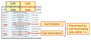
b) No packets that could be considered abnormal were found from the analysis of packet-capture data. However, packet sequences also revealed calls in which the time interval from call initiation to termination was less than one second, which was in agreement with the VoIP-GW call log. These results are shown in Fig. 4.
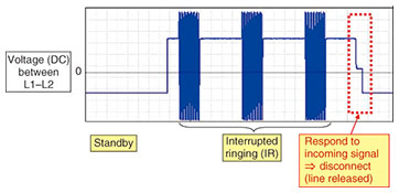
c) At the times this fault occurred, signal monitoring between the VoIP-GW and PBX equipment revealed that the line would disconnect immediately after the PBX responded to the interrupted ringing (IR) signal sent by the VoIP-GW. The signal waveform at this time is shown in Fig. 5.
2.1.5 Cause of faultGiven that all incoming-call responses and disconnect operations were normal up to the analog-interface section between the VoIP-GW and PBX equipment, we surmised that a problem existed on the PBX side. We considered, for example, that a defective hook switch on a specific extension phone to the PBX could cause the line to disconnect when responding to an incoming call. 2.1.6 Countermeasure and effectTo further troubleshoot this fault, we decided to equip the PBX with a function for saving and managing the call history, which would enable us to collect and analyze data and thereby identify the extension phone of the PBX that was disconnecting the line when responding to an incoming call. The results of troubleshooting after implementing this countermeasure showed that the cause of this fault was an operational error by the customer of this PBX. In other words, the cause of this fault lay on the PBX side as we had surmised. 2.1.7 SummaryIn this inspection, we collected and analyzed the VoIP-GW call log and inferred that equipment positioned below the VoIP-GW was disconnecting the calls. Although checking the analog-interface interval with instrumentation normally used in fault troubleshooting presents some difficulties, checking the logs of various types of equipment is relatively easy and makes for a useful and important fault-troubleshooting technique. 2.2 No ringing sound when the PBX receives an outside call2.2.1 Equipment configurationThis configuration was the same as that in the fault case described in 2.1. 2.2.2 Fault descriptionAfter the analog line was changed over to Hikari Denwa, sometimes no ringing would occur at the time of an incoming call even though the caller could hear a ring sound. It had already been confirmed that this would not occur if the IVR equipment were disconnected. 2.2.3 Inspection methodAfter confirming the occurrence of no incoming-call ringing in an on-site incoming-call connection test, we configured some test equipment and conducted a reproducibility experiment. This configuration is shown in Fig. 6.
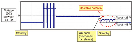
a) In this reproducibility experiment, we monitored signals in the analog-interface section between the VoIP-GW and PBX equipment using an oscilloscope while varying the resistance using a variable resistor in place of the IVR equipment. b) We examined the conditions under which no ringing occurred when a call came in from the outside. 2.2.4 Inspection resultsa) Signal monitoring in the analog-interface section revealed the following. If the value of DC (direct current) resistance between the L1–L2 lines at the time of circuit release happened to be less than 0.74 MΩ, the potential between L1–L2 would become unstable, fluctuating roughly between –48 V and –28 V directly after the on-hook operation*. The waveform at this time is shown in Fig. 7.
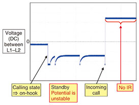
b) We confirmed that no IR signal would be issued if an incoming-call polarity reversal occurred while the L1–L2 potential in the analog-interface interval was unstable. The waveform at this time is shown in Fig. 8.
2.2.5 Cause of faultSpecifications of the VoIP-GW installed on the customer’s premises stipulated various electrical conditions with respect to branch connections, so we checked whether the customer’s equipment setup conformed to those conditions. One of the conditions was that the value of DC resistance between L1–L2 was to be 1 MΩ or greater, but we found from measurements that the value was only 0.6 MΩ. We therefore surmised that VoIP-GW operation would be unstable and that this fault would occur since the stipulated conditions for branch connections were not being observed. 2.2.6 Countermeasure and effectThe countermeasure that we implemented to keep DC resistance between L1–L2 at 1 MΩ or greater and to prevent this fault from occurring was to install a switching device instead of branch connections and to apply a switching method to be used in the PBX and IVR equipment. 2.2.7 SummaryWe surmised that no ringing occurred when receiving calls from the outside since branch-connection conditions stipulated in the specifications of VoIP-GW equipment installed after the change from an analog line to Hikari Denwa were not being observed.
3. ConclusionThis article introduced two case studies of faults occurring in an IP phone circuit accommodating a PBX via a VoIP-GW. The first case was solved by analyzing a call log and the signals/packets in the analog-interface/Ethernet sections. In the second case, investigating the customer’s network system to determine whether it satisfied the required specifications led to the solution. To achieve these troubleshooting results, it is necessary to be familiar with analog and IP technologies as well as the equipment or system requirements. With current technologies, a switchover to an analog interface can occur by using a VoIP-GW when accommodating a PBX in an IP phone circuit, so it is essential that knowledge of legacy systems in addition to that of IP systems be brought to the troubleshooting process. |
||||