 |
|||||
|
|
|||||
|
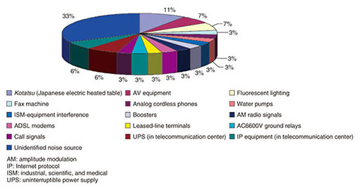
Practical Field Information about Telecommunication Technologies Vol. 12, No. 10, pp. 70–74, Oct. 2014. https://doi.org/10.53829/ntr201410pf1 Signal Generator for Noise Search Tester to Improve Noise-measurement and Noise-identification SkillsAbstractThis article introduces recent equipment and methods developed for use in troubleshooting noise faults. This is the twenty-fifth of a bimonthly series on the theme of practical field information on telecommunication technologies. This month’s contribution is from the EMC Engineering Group, Technical Assistance and Support Center, Maintenance and Service Operations Department, Network Business Headquarters, NTT EAST. Keywords: noise faults, noise measurement, maintenance skills 1. IntroductionThe objective in the development of electric and electronic devices in recent years has been to make them smaller and more energy efficient. Meeting this objective, however, results in heavy use of the switching circuit in the power-supply section of such devices. This means that noise caused by the operation of the switching circuit or by problems in capacitors, semiconductors, or other circuit devices may be conducted to the outside via power or communication lines or radiated through space. Noise of this type can generate audible noise in telephone calls in the user’s building or home or can bring down a communication link in ADSL/VDSL (asymmetric digital subscriber line/very-high-speed DSL) lines as a result of a communication coding error or other fault. In this situation, some type of countermeasure must be taken such as installing appropriate noise filters in the power or communication lines connected to the telephone equipment or by removing the noise sources themselves. In any case, measuring the frequency and levels of the disturbance voltage (or current) superimposed on power or communication lines is necessary for the troubleshooting process. It is for this reason that we developed a noise search tester (NST) that can be easily used by on-site maintenance operators. We have also marketed a successor to this product (NST II) that features enhanced sensitivity to periodic burst noise. More than 1000 units of the NST series have so far been introduced into the market. In order to look for the noise source, it is necessary to conduct the noise measurement in complex facility environments that include not only telecommunication equipment but also various types of power-supply devices. It is therefore important that maintenance operators improve their skills in conducting measurements with NST II. In this article, we present a case study of a malfunction of telecommunication equipment and describe our development of a signal generator designed for simulating actual noise waveforms. 2. Case study2.1 Noise sourcesNoise sources that can lead to faults can exist in a wide variety of electric and electronic devices in addition to communications equipment. Identifying a noise source can therefore be quite difficult. Types of noise sources found in a two-year on-site survey are shown in Fig. 1. It can be seen from the figure that electric and electronic devices that use alternating current (AC) mains power, for example, a Kotatsu and AV (audio-visual) equipment, can be a source of noise. However, because a variety of electric and electronic devices are usually connected to the same AC mains line, it has been extremely difficult to identify where the noise source is actually located. The following section presents a case study of a noise-induced fault describing how the noise source was identified and what countermeasure was taken.
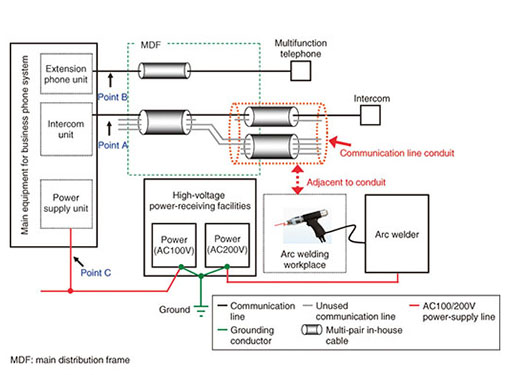
2.2 Case study of noise-induced fault2.2.1 Fault overviewA customer using business phones reported a fault in which an audible noise would sometimes be heard during telephone calls. The facility setup on the customer’s premises is shown in Fig. 2. Although a maintenance operator spoke with the customer a number of times to determine the cause of the fault, the fault remained, and it was eventually decided to perform on-site noise measurements and consider countermeasures.
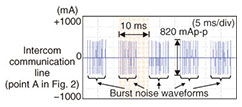
2.2.2 Noise measurementThe maintenance operator performed noise measurements at several locations (points A–C in Fig. 2) and measured, in particular, disturbance current using an oscilloscope and current probe. The noise waveforms at the intercom communication line (point A) are shown in Fig. 3.
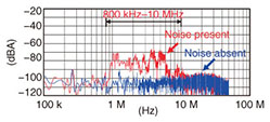
(1) The noise waveforms depicted typical periodic burst noise that was generated every half cycle (10 ms) with respect to the frequency of AC mains power (50 Hz). An on-site inspection revealed that this noise was generated when arc welding work was being done. It was also found that disturbance current values were highest on the intercom communication line (point A in Fig. 2) situated adjacent to the arc welding workplace. (2) The results of performing FFT (fast Fourier transform) analysis on the measurement results of Fig. 3 and determining its power spectrum are shown in Fig. 4. In comparing the state in which noise was present with the state in which noise was absent, it was found that the noise level was high across a wide frequency range of 800 kHz–10 MHz.
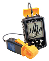
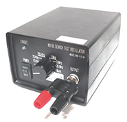
These measurement results indicate that the fault occurred during the arc welding operation. In addition, the results of more detailed measurements revealed that this noise was transmitted to the business phone from the intercom communication line near the arc welding workplace, and it then flowed into other communication lines and AC mains lines. 2.2.3 Noise countermeasureThe following actions were taken as a countermeasure to this noise: (1) Unused multi-pair in-customer-premises cables near the arc welding workplace were removed. (2) Noise filters were installed on communication lines on the business-phone side and on the side of terminals connected to the business-phone side. (3) A transformer was installed on the business-phone AC mains line; the ground terminal and the business-phone FG (frame ground) terminal were connected, and these were connected in turn to the MDF (main distribution frame) ground, keeping the connection as short as possible. The above countermeasure made it possible to eliminate the audible noise from the business-phone side. Nevertheless, the on-site maintenance operator said that we had had few encounters with a noise-induced fault of this type, which meant that they had no opportunities to practice troubleshooting or dealing with this kind of problem, even employing an easy-to-use measurement tool like the NST II. We therefore realized that a tool that could facilitate the acquisition of necessary skills when using NST II had to be developed. 3. Signal generator for use with a noise search tester3.1 Development backgroundGiven the occurrence of audible noise in telephone calls or of link down in ADSL/VDSL lines, an experienced maintenance operator would be able to measure noise using NST II (Fig. 5) and then identify the source of the noise and implement appropriate countermeasures with noise filters. An on-site maintenance operator needs noise-measurement skills to appropriately identify the noise source and to select noise filters when using NST II. For this reason, we have been engaged in technology dissemination activities by creating a noise fault environment using a signal generator so that maintenance operators can acquire the skills needed for troubleshooting and identifying noise sources and for selecting appropriate countermeasures. Maintenance operators who have wanted to improve their noise-measurement skills on their own have been faced with a number of problems, which is reflected by comments received from them such as “Signal generators are too expensive” and “Creating a noise environment is too difficult.” In the face of these problems, we developed a signal generator for use with a noise search tester that can easily and inexpensively create noise environments for training purposes (Fig. 6).
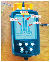
3.2 FunctionsThis signal generator has been designed to enable simulated noise to be safely and easily measured when used in combination with NST II. Two important points in the development of this signal generator are described below. (1) Triangular-wave signals The signal generator can output seven types of triangular-wave signals corresponding to the NST II frequency range. It was decided to use triangular-wave signals since the high harmonic components of noise cannot be simulated in the case of sinusoidal signals. The specific signal frequencies that can be output are 1 kHz, 15 kHz, 70 kHz, 250 kHz, 1 MHz, 3 MHz, and 20 MHz, which means that the signal generator can simulate signals that approximate those of actual noise waveforms (Fig. 7).
(2) Signals that simulate burst noise on AC mains line The signal generator can output signals that simulate the periodic burst noise (half cycle of the frequency) on an AC mains line. This type of noise has become the chief cause of noise-related faults in recent years. When selecting a simulated noise signal, the user can listen to a whirring sound representing noise by connecting an earphone to the NST II for monitoring purposes. The signal generator described above enables maintenance operators to improve their noise measurement skills using NST II by making it possible to easily create a noise environment that is similar to one with actual noise faults. 3.3 Usage of the signal generatorA typical setup for this signal generator, NST II, and telecommunication equipment is shown in Fig. 8. In this figure, the signal generator directly applies noise to the communication cable, and a maintenance operator uses NST II to measure that noise. By checking for the frequency of the NST II, the maintenance operator can apply an appropriate countermeasure. This signal generator therefore makes it easy to create an environment in which maintenance operators can practice searching for the noise source and decide what countermeasure to take against the noise fault, which has been difficult to do in the past. We expect repeated practice with such simulated noise to enable maintenance operators to solve noise faults on communication cables.
4. ConclusionSolving noise-induced faults in a system requires troubleshooting skills in identifying the source of the noise as well as skills for taking appropriate countermeasures. To meet these requirements, we developed a signal generator for use with a noise search tester as an effective means of creating a noise environment at low cost and to enable maintenance operators to acquire noise measurement skills while using NST II. Going forward, we plan to continue our research and development efforts to facilitate speedy solutions to noise-related problems and provide enhanced support for safe and secure communication services. References
|
|||||


