|
|||
|
|
|||
       |
Regular Articles Vol. 12, No. 10, pp. 54–58, Oct. 2014. https://doi.org/10.53829/ntr201410ra2 Development of Long-span Aerial Cable Installation Technique (Long Hanger Method)AbstractWe have developed a technique called the long hanger method for installing a long span aerial cable across, for example, a valley or river without using conventional methods that require special skills or installation tools. Our new method enables us to easily overlay or replace cables. Keywords: long-span aerial cable installation, rural area, overlay/replace cables
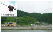
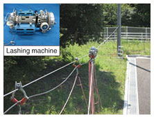
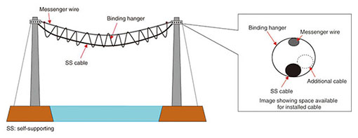
1. IntroductionWhen optical services were being developed for NTT EAST and NTT WEST, optical equipment was deployed throughout the country. Facilities were already adequate in most urban areas, so the development of rural areas was planned for the future. The environment in rural areas is different from that in urban areas in terms of the distances between NTT buildings and customer premises, as well as customer density. Therefore, we require components and installation methods that are suitable for rural environments. An example is the aerial cable installation technique used for 200- and 250-m long-span sections over valleys or rivers. Conventionally, we use a catenary method or a lashing method, but they give rise to the following two problems. (1) Installation The catenary method requires a special skill (the ability to do aerial work) for construction to be completed safely (Fig. 1). The lashing method requires a special tool (lashing machine). The widespread application of this tool ended decades ago, and it is now only required for long-span sections (Fig. 2). Today, few engineers have the skill required to do aerial work, and lashing machines that meet NTT specifications are no longer produced. Therefore, it will be difficult to continue using these methods in the future. In addition, the catenary method was used for cable restoration work after the Great East Japan Earthquake, and it took a long time to secure the required personnel and to conduct the preparatory work for building the facilities. Therefore, new technology is needed that can reduce the cable restoration time.
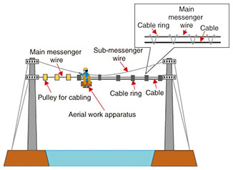
(2) Components With these conventional methods, overlaying or replacing a cable takes an equivalent amount of time as that originally needed to install the same components because of the difficulty in installing an additional cable. We have developed the long hanger method as a solution to these two problems. 2. New development conceptWe first explain the problems regarding the catenary and lashing methods. The components used with the catenary method consist of two messenger wires (a main messenger wire and a sub-messenger wire), a cable, and cable rings (Fig. 3). It is necessary to do aerial work (i.e., to work in mid-air) using a specially designed apparatus when fixing the main messenger wire to a sub-messenger wire during the temporary installation of a cable, and when attaching cable rings. This is also the case when we install an additional cable, where we must remove and reattach cable rings individually. This means that it takes a long time to install an additional cable. Replacing the cable takes even more time because we have to remove the cable in addition to carrying out the above process.
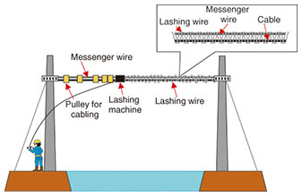
The lashing method was developed to eliminate the need for aerial work. The lashing method employs a messenger wire, a cable, and a lashing wire (Fig. 4). In the installation, we first place a lashing wire in a lashing machine and then fix a messenger wire and a cable in place with the lashing wire. The lashing machine can be used over a long-span section, so aerial work is not required. However, lashing machines that meet our specifications are no longer being produced, and therefore, we cannot continue to use this method. In addition, if we overlay a cable using the lashing method, it will be necessary to carry out the installation of a messenger wire, a cable, and a lashing wire as if it were a new installation, which would take a long time. Replacing the cable takes even more time because we have to remove the existing cable in addition to completing the above installation process. Our aim with the long hanger method was to employ the binding hanger used for conventional aerial sections and create a space in which we can overlay and remove cables freely without the need for aerial work or a special tool. We developed a safe installation technique for 250-m spans and highly reliable equipment that can be used in various environmental conditions such as strong winds.
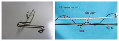
3. Required componentsThe components required for the long hanger method include a messenger wire, a binding hanger, and cables (Fig. 5). The role of the messenger wire is to support the load of all components as well as the load applied by wind pressure. The binding hanger creates a space in which we can freely overlay or remove cables. From several types of binding hangers, a cosine curve hanger (CCH) is used in this method because it can be coiled up compactly even if it is long. A stopper is used to fix the CCH to the messenger wire, which further improves the reliability (Fig. 6). This stopper prevents the CCH from moving away from the messenger wire and prevents cables from falling out of the CCH because the internal space of the CCH is enclosed. A self-supporting (SS) cable is used to prevent fiber movement and fiber strain.
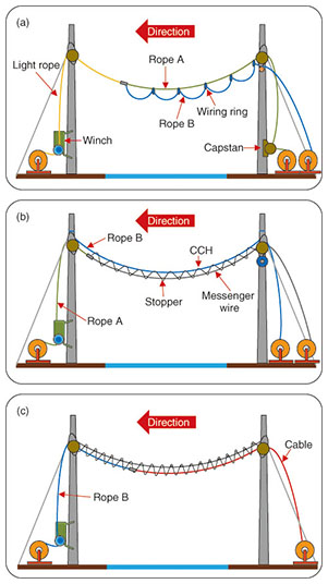
4. InstallationIn a standard aerial section, we first install a messenger wire and then a CCH by pushing the CCH out along the messenger wire from a given pole. However, if we want to install a CCH in a log-span section, we cannot get it all the way over to the other pole because the friction against the messenger wire increases with a slack and steeply pitched messenger wire. Alternatively, when we pull a CCH from one side, it can be stretched as a result of the large tension. This reduces the internal space of the CCH and makes it impossible to overlay and replace cables. With the long hanger method, we install a messenger wire and a CCH simultaneously. This approach reduces the tension on the CCH and makes it possible to get the CCH all the way over to the other side. The procedure is as follows: (1) A light rope is first installed between the poles (the same process as in the conventional method). (2) Two ropes are then installed between the poles by connecting them both to the first light rope and pulling it. (Fig. 7(a)). Rope A: messenger wire Rope B: SS cable Wiring rings are used to lift rope B across a long span. (3) A messenger wire and a CCH are installed by pulling rope A and adding stoppers (Fig. 7(b)). Rope B is fixed to the poles, and it prevents the messenger wire and CCH from falling down between the poles of the long span section. A conventional winch can be used for this process because rope B can reduce the tension needed to pull the messenger wire and the CCH. (4) Tension is applied to the messenger wire, which is then fixed to the poles; a space has been included for freely overlaying and removing cables. (5) An SS cable is installed by connecting it to rope B and then pulling on rope B (Fig. 7(c)). (6) The SS cable is fixed to the poles.
5. Overlaying/replacing a cableIn a conventional aerial section, when we overlay or replace a cable, we use a wiring method that involves pushing a shuttle that carries the wire from one side and passing it through the CCH. However, we cannot use this approach in a long-span section because the shuttle falls from the CCH as a result of the large amount of slack. Therefore, we adopt an approach where a wire is installed at the same time the cable is first installed. In this way, we can pass the CCH through without fail and eliminate the later wiring process. 6. ConclusionThe long hanger method is highly versatile because the tools it requires—namely, ropes, a winch, and so on—are in general easily available. In addition, we confirmed the high reliability of the components used in this method, which is important since they are exposed to extremely windy environments with large temperature fluctuations. This method is scheduled to be introduced in 2014 by NTT EAST and NTT WEST. We will assist each company with its introduction. |
||