 |
|
|
|
|
|
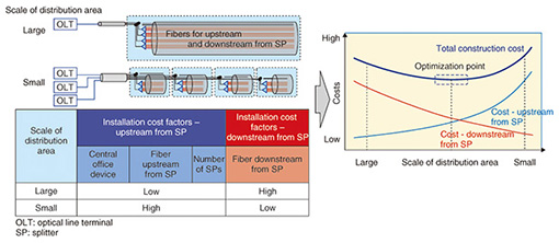
Regular Articles Vol. 12, No. 12, pp. 37–42, Dec. 2014. https://doi.org/10.53829/ntr201412ra2 Development of Optical Access Network Systems in Rural AreasAbstractWe have developed a technique and equipment for installing optical cables and closures. The technique is optimized according to the characteristics of the area in order to reduce the construction cost of the facilities architecture and promote fiber-to-the-home services. Keywords: rural areas, simple installation technique, FTTH 1. IntroductionIn Japan, the number of fiber-to-the-home (FTTH) service subscribers now exceeds 23 million. However, there are still some areas where FTTH services are not provided, and therefore, further expansion is expected. The expansion of FTTH services has been focused mainly on urban areas, so the focus is now on rural areas such as small towns. In rural areas, there is less demand for these services than in urban areas of the same geographical size. Therefore, the construction costs for optical access network architecture in rural areas are much higher than in urban areas (Fig. 1). In future, to make the deployment of FTTH services economical for rural areas, an optical access network configuration technology is needed that will minimize the construction cost by taking account of regional aspects. In particular, a reduction of the cost of installing optical fiber cables on poles is required because it accounts for half the construction cost of facilities.
2. New development conceptWe investigated ways of reducing the construction cost of facilities by focusing on the following two schemes. (1) Optimization of the distribution area The size of a distribution area is based on the number of users in that area, and the size affects the construction cost, especially the aerial cable cost. Therefore, we simulated the relationship between the construction cost and the size of the distribution area. When there are more users in a large area, the amount of cable conductor for the segment downstream from the splitter increases with the number of users and the distance to each user. In contrast, when the area is smaller, the distance to each user is reduced; it is then possible to reduce the amount of cable conductor from the downstream. The amount of cable conductor for the upstream segment from the splitter, and the number of corresponding devices in the central offices are increased if the distribution area has a small configuration. Therefore, we must take the above problem into consideration and configure the optimal distribution area in various locations. If we calculate the optimal relation between the construction cost and the scale of the distribution area in rural areas, then we can optimize the amount of facility construction and reduce the construction cost (Fig. 2). For example, if the amount of cable conductor needed for the downstream segment from the splitter is reduced, we can apply 24-fiber cable in a zone where 40-fiber cable has been installed in the past.
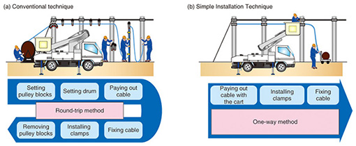
(2) Development of Simple Installation Technique If the total length of cables installed in rural areas is long, the cost of cable installation will be too expensive because the conventional installation uses a round-trip method. Therefore, we needed a one-way installation technique in order to reduce the cost of cable installation (Fig. 3(a)). However, to make one-way cable installation practical, we need a technique for paying out and installing the cable at the same time as well as an effective technique to secure the cable to telephone poles. We came up with a technique that employs lightweight optical cable, which means the cable drum is also lightweight. We have named this technique the Simple Installation Technique. The total weight of all the components is less than 50 kg, so we can install the cable while moving the drum with a cart. When we applied our technique, we were able to install cable using a one-way method by installing cables on telephone poles at each span, in contrast to the previous round-trip method. Thus, we were able to reduce the number of workers usually needed for this task, as well as the working time, and achieve a reduction in the total amount of work (Fig. 3(b)).
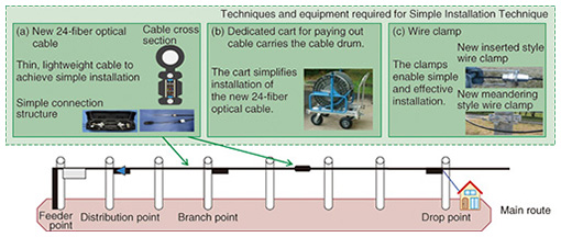
3. Equipment used in Simple Installation Technique3.1 New 24-fiber optical cable (Fig. 4(a))We developed a cable unit (cable and cable drum) that does not exceed 45 kg by reducing the weight of the conventional 24-fiber optical cable by 60%. The total cable length of the cable drum is 500 m. Therefore, it is possible to install the cable while concurrently moving the drum with a dedicated cart. Also, when we connect segments of the new 24-fiber optical cable together, we do not need to use any tools because there are MPO (multiple-fiber push-on/pull-off) connectors at both ends of the 24-fiber cable. NTT EAST and WEST have been using this cable since 2013 because it costs less than the conventional cable. 3.2 Dedicated cart for paying out cable, and new wire clamps (Figs. 4(b, c))We developed a dedicated cart that is necessary when the above described cable is installed using the Simple Installation Technique. The cart has a characteristic design consisting of four tires to enable humans to push it on various kinds of roads, a hole to pay out the cable, and a stopper to prevent backlash. We also developed two new types of wire clamps that are needed to clamp the above described cable to a pole when it is installed using the Simple Installation Technique. One clamp is referred to as inserted style and is used to fix the installed cable to terminal poles. The other clamp is the meandering style and is used at intermediate poles. Both clamps are necessary in the Simple Installation Technique because the technique involves a one-way procedure, and we must install the cable on telephone poles at each span.
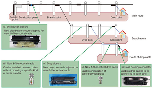
4. Components developed for Simple Installation TechniqueWe developed several new components for the Simple Installation Technique. We describe them in this section. 4.1 Distribution closure (Fig. 5(a))We developed a new distribution closure that is miniaturized compared to conventional closures. This is because it needs to house fewer splitters due to the optimized distribution area. Moreover, this distribution closure can be used with thin and lightweight 24-fiber optical cable. Therefore, the price of this closure is lower than that of conventional closures. Another advantage of this closure is that it enables either a fusion splice, which is economical for optical fiber connections, or a mechanical splice, which makes it possible to supply the optical network service with respect to the demand from each customer when we connect downstream fibers to distribution fibers in the closure. 4.2 New 8-fiber optical cable (Fig. 5(b))The new 8-fiber optical cable we developed can be installed between poles without a wire grip. This cable is as thin as the conventional 8-fiber drop cable. Therefore, we can reduce the price of the components and the cost of installing this cable compared with the conventional 8-fiber optical cable. We can also use the conventional cable installation tool by adding an attachment to it. 4.3 Drop closure (Fig. 5(c))We developed a drop closure that is the smallest in Japan and is lighter in weight than all conventional closures. This closure accommodates only two 1-fiber drop cables. Therefore, we were able to reduce its volume by 90% compared with the smallest conventional closure. We also developed the Simple Splice Technique in order to connect a distribution fiber to a fiber in the drop cable even inside this small closure. In addition, we developed a closure for use in connecting the new 8-fiber optical cable or conventional ribbon drop cable. This closure is used when poles are moved and the cables installed on the poles need to be replaced due to the construction of network facilities, and also when the above cables are severed on account of a traffic accident. 4.4 Thin and SZ twisted optical drop cable (Fig. 5(d))We developed new 1-fiber optical drop cable with a twisted SZ form that helps to reduce the force of wind pressure. We also strengthened the supporting wire so that we could install a drop cable between poles. These characteristics reduce the cost of facility installation because it is no longer necessary to install closures near customer homes when this drop cable is installed between the conventional closures and customer homes. Furthermore, the development of this drop cable is in line with the policy promoted by NTT EAST and WEST to build facilities that are resistant to natural disasters, and therefore, this drop cable has been installed in some areas by NTT EAST and WEST since 2013. 4.5 Case housing connector (Fig. 5(e))We developed the case housing connector in order to connect the drop cables together. This case has been used by NTT EAST since 2013 and is contributing to reducing the cost of drop cable replacement.
5. ConclusionWe have developed a cable closure that can be used with lightweight cables, as well as a new Simple Installation Technique. These developments have helped to achieve a facilities architecture that is optimized to the characteristics of specific areas and enables more efficient facility construction. Consequently, we can reduce the construction cost in areas where it was conventionally high and where service provision was difficult. These achievements will allow us to further promote FTTH services. |
|


