|
|||||||||
|
|
|||||||||
       |
Feature Articles: Transport Network Management Platform Technology Vol. 13, No. 10, pp. 33–37, Oct. 2015. https://doi.org/10.53829/ntr201510fa4 EMS Development and Deployment Using Transport Network Management Platform TechnologyAbstractNTT Network Service Systems Laboratories is promoting practical development of element management systems (EMSs) for various network elements by focusing on transport network elements and taking advantage of the transport network management (TM) platform technology we developed. We developed EMSs by using TM platform technology (TM-EMS) in order to integrate a human-machine interface for each network-element operation system, provide a unified interface for the network management system, and enable efficient flow-through operation. We introduce the EMSs we developed in this article. Keywords: element management system, practical development, TMF513
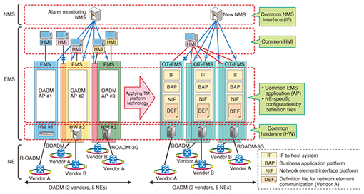
1. IntroductionDevelopment of element management systems (EMSs) for various network elements (NEs) has been underway at NTT Network Service Systems Laboratories since 2011, when we developed an EMS for optical add/drop multiplexers (OADMs). We introduce here the EMSs we developed using transport network management (TM) platform technology (TM-EMS), and we describe the NEs the EMSs manage. 2. TM-EMS for OADM2.1 BackgroundAn OADM is a transport network element that can multiplex optical signals and transport data to distant places. In NTT’s transport network, three types of OADM NEs are in operation—reconfigurable OADM (R-OADM), broadband OADM (BOADM), and ROADM third generation (ROADM-3G)—and they are fabricated by several different vendors. Consequently, at one stage, we needed to operate five different kinds of OADM NEs. This complex configuration motivated us to apply TM platform technology to develop an EMS for OADMs because the support for servers of the old network-element operation system (NE-OpS) for OADMs was scheduled to end. Our objective was to use a TM-EMS to integrate a human-machine interface (HMI) for each current NE-OpS for OADMs and provide a unified interface for a network management system (NMS) to enable flow-through operation (Fig. 1). The TM-EMS for OADMs (called an OT-EMS) has been in use at NTT EAST since April 2013 and NTT WEST since June 2013.
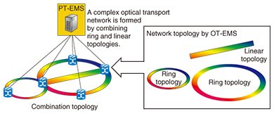
2.2 Technical featuresTo meet the requirements of a new EMS for OADMs, the OT-EMS should have two features that are similar to the old NE-OpS. One is the optical path management function and the other is the HMI operation for the OT-EMS. We used the object model included in TMF513, the business agreement on multi-technology network management issued by the TeleManagement Forum [1], as the basis of the OT-EMS specifications. TMF513 specifies two types of objects: logical objects and physical objects. Logical objects represent information on path connections such as the termination point and cross-connection point of a signal. The termination point represents the input/output of the signal point, and the cross-connection point represents the connection between two termination points. Physical objects represent information on components including hardware packages and optical modules. When an EMS configures an optical path, it requires physical package information on optical path routes. The EMS needs to link logical objects to physical objects. To set up an optical path to NEs, we defined these objects by understanding the details of each transport network element specification. In addition, we expanded the TMF513 object model by adding other objects, for example, area and building, which are necessary for NTT’s network management. These objects are used by all of the TM-EMSs. 3. TM-EMS for 100G-PTS3.1 BackgroundThe 100-Gbit/s packet transport system (100G-PTS) is a new transport network element that enables the construction of more flexible and efficient networks. It has two function blocks. One is the optical transport function block, which supports 100-Gbit/s broadband optical paths, and the other is the packet transport function block, which supports the Multiprotocol Label Switching-Transport Profile (MPLS-TP). We developed a TM-EMS for 100G-PTSs (called PT-EMS) to manage both function blocks of 100G-PTSs. The network model of the PT-EMS is an expansion of the optical network model in the OT-EMS specification. The PT-EMS has been in use at NTT EAST since November 2014 and at NTT WEST since June 2015. 3.2 Technical featuresWe can represent the optical paths as a ring or linear topology in the OT-EMS because the OADM NEs can only set up to two transport routes. In contrast, the 100G-PTS NEs can construct more complex topologies because they can set as many as eight transport routes. We can represent optical paths in the PT-EMS as a ring, linear, or new topology, which is a combination of ring and linear topologies. Moreover, we can represent it not only as an OADM network but also as a more complex network that has more than three transport routes (Fig. 2).
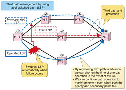
In managing packet transport function blocks, we use objects in the TMF513 object model; this is similar to the use of NEs, packages, and path termination points in MPLS-TP path management. Therefore, we can provide an MPLS-TP path management flow that is similar to an optical path management flow by taking advantage of the OT-EMS specifications. In addition, the PT-EMS provides a switching function to the third path (Fig. 3). In path operation, the NEs can construct a network with redundancy by specifying priority and secondary paths in the event of path defects or failures. In addition, we can reserve the third path in the PT-EMS. If the priority or secondary path is defective, we can maintain redundancy with the third and non-defective paths. The PT-EMS provides a sequential screen transition for the switching function to the third path. Therefore, operators can quickly deal with defects and disasters without having to carry out a complicated procedure. This function is provided in the NEs in the PT-EMS but not in the 100G-PTS.
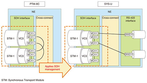
4. TM-EMS for PTM-XC4.1 BackgroundThe NEs of the Packet Transport Multiplexer cross-connect (PTM-XC) are based on the PTM link system [2], and they have cross-connect functions that can connect lower-order paths (VC-11 and VC-2) by using packet transport technology based on the MPLS-TP on the synchronous digital hierarchy (SDH) network. We can manage the NEs of the PTM-XC by configuring the SDH paths. Therefore, we developed a TM-EMS for PTM-XC (called PX-EMS) by applying TM platform technology to an optical path and MPLS-TP path management. The PX-EMS has been in use at NTT EAST and NTT WEST since September 2014. 4.2 Technical featuresWe added some new logical objects to the TM platform technology to manage the SDH NEs in the PX-EMS. To manage the SDH paths and the NEs of the PTM-XC, we can split and reassemble individual low-speed paths and can register and read test points. Therefore, we added the termination point object of VC-11, which is the SDH low-speed path, as an expansion of the object model in TMF513 in the PX-EMS. 5. TM-EMS for SYS-U5.1 BackgroundTo provide communication procedures on remote islands and in areas affected by natural disasters, NTT EAST and NTT WEST operate a satellite communication system with a satellite connection defined in Recommended Standard-422 (RS-422). The communication devices used in the satellite communication system have become older, and therefore, NTT developed a high-efficiency satellite connection terminating element called SYS-U (system unit). This element assembles the SDH termination function, echo canceller function, and modem function. Using the SYS-U makes it possible to simplify the network and enables more efficient satellite connections. The SYS-U terminates the (V)C11* path as a satellite connection and communicates via the SDH optical signal. The SYS-U’s units of communication, alarm, and cross-connection are the same as those of the NE of PTM-XC. Consequently, we decided to use the same object model as that specified in TMF513 (Fig. 4).
By taking advantage of the TM platform technology, we developed a TM-EMS for SYS-U (SAT-EMS). 5.2 Technical featuresWe applied TM platform technology to optical paths, MPLS-TP and SDH paths, and we expanded the TMF513 object model. We achieved a highly efficient satellite connection terminating element by developing the SAT-EMS by using the object model in TMF513 in the (V)C11 and VC-11 paths. The SAT-EMS can configure lower-speed channels (64 kbit/s) than the VC-11 path (1.5 Mbit/s) in the PX-EMS.
6. Future prospectsWe have expanded the TM platform technology with practical development of EMSs for various NEs. In the future, we plan to conduct research and development to promote more efficient development of EMSs by using our expanded TM platform technology. We will also work on improving this technology in order to apply it to EMSs and increase the common functionality of the TM-EMS. References
|
||||||||