|
|||||
|
|
|||||
       |
Practical Field Information about Telecommunication Technologies Vol. 13, No. 10, pp. 64–69, Oct. 2015. https://doi.org/10.53829/ntr201510pf1 A Case Study of a Problem that Occurred in Downstream Device of VoIP GatewayAbstractThis article describes a problem that occurred in a VoIP (voice over Internet protocol) gateway and the actions taken to rectify it. This is the thirty-first article in a bimonthly series on practical field information on telecommunication technologies. This month’s contribution is from the Network Interface Engineering Group, Technical Assistance and Support Center, Maintenance and Service Operations Department, Network Business Headquarters, NTT EAST. Keywords: VoIP gateway, Hikari telephone, analog terminal
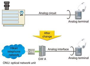
1. IntroductionA voice over Internet protocol (VoIP) gateway unit (GW) enables existing terminal facilities to use VoIP circuits without having to be upgraded after introducing optical facilities in the upstream access network. This approach enables VoIP service to be implemented at a relatively low cost and to be widely used by a large number of users, from general users to business/office users. Such terminals have been used with the conventional telephone network (analog, ISDN*, etc.) without any problems. However, we have been consulted on communication problems that occurred when the upstream access network was upgraded to optical facilities. In this article, we refer to an actual case study to explain how such problems might occur.
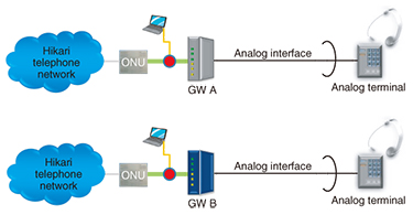
2. Case studyIn this case study, a terminal connected to the analog port of the GW was unable to make an outgoing call. 2.1 Event conditionsA customer who had undergone a change from an analog telephone system to an office-type VoIP telephone system (Hikari telephone system) reported events in which a terminal connected to the GW could not make an outgoing call. Specifically, if an outgoing call to a telephone number that included the numbers 1, 2, 3, or 6 was attempted on the push-button panel, a busy tone would be heard after a certain amount of time after dialing, and no connection would be made. The customer informed us that they had not had any problems with their terminals before changing to the Hikari telephone system. An attempt was made to solve this problem by replacing GW A with equipment of the same model, but the problem persisted. However, when GW A was replaced with GW B, the problem went away. We therefore performed a series of tests to determine why calls could not be made with GW A but could be made with GW B (Fig. 1).
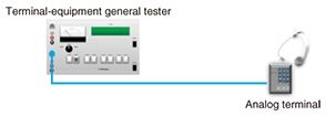
2.2 Overview of testsAfter setting up facilities similar to those of the customer’s in which the problem occurred, we performed the following tests. (1) Replication test by connecting an analog terminal to analog port of GW A and GW B (test 1) The method used here for originating a call from an analog terminal was to press all push buttons 1–9 and 0 in an off-hook state. The telephone number that was recorded in the communication log of the GW was then compared to that obtained through packet capture in the upstream interval between the GW and the optical network unit. (2) Terminal evaluation using terminal-equipment general tester (test 2) The analog terminal was evaluated to determine whether it satisfied the technical standards set down by Japan’s Ordinance Concerning Terminal Facilities (Ordinance of the Ministry of Posts and Telecommunications No. 31, 1985) as follows. 1) Requirements for push-button signals: Article 12, Item 2 2) DC (direct current) resistance value when closing DC circuit (electrical requirements of DC circuits etc.): Article 13, Item 1 (3) Event replication check when changing facilities upstream of the terminal to something other than GW A and GW B (test 3) This test was done to check whether the same kind of event could be replicated when connecting the target analog terminal to a simulated analog circuit using a telephone circuit simulator. 2.3 Descriptions and results of tests2.3.1 Test 1(1) Description We conducted a call-originating experiment connecting the analog terminal to GW A and GW B (Fig. 2) and performed the following actions.
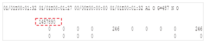
1) The communication logs (internal logs of GWs A and B) were collected and recorded during the experiment. 2) Information on the state of communication at the time of the experiment was collected through packet capture (red dot in figure denotes the capture point). (2) Results First, the logs and the capture data of connecting the analog terminal to GW B and pressing push buttons 1–9 and 0 revealed that all signals corresponding to those buttons were confirmed. The results of connecting the analog terminal to GW A and pressing push buttons 1–9 and 0 are summarized below. 1) Push-button signals 2, 3, and 6 were not recorded in the communication log (Fig. 3).
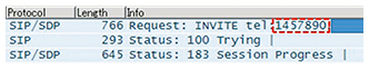
2) Likewise, information on numbers 2, 3, and 6 were not recorded by packet capture (Fig. 4).
2.3.2 Test 2(1) Description In this test, we conducted measurements using a terminal-equipment general tester to determine whether the terminal satisfied the following technical standards specified by the Ordinance Concerning Terminal Facilities (Fig. 5).
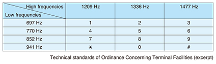
1) Requirements for push-button signals (Tables 1 and 2)
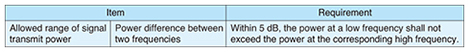
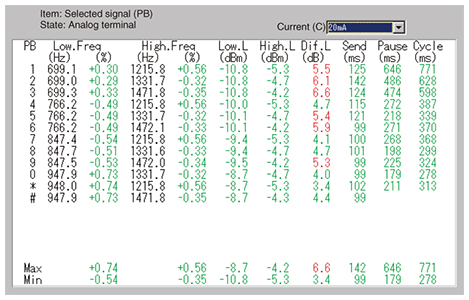
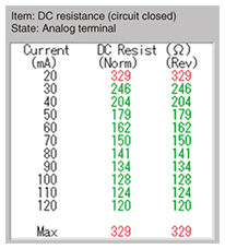
2) Electrical requirements of DC circuits: When measuring the loop current in the range from 20 mA to 120 mA, “the DC resistance value of the DC circuit of the analog terminal with the DC circuit closed shall be in the range from 50 Ω to 300 Ω.” (2) Results 1) Results of measuring power for a current of 20 mA using the terminal-equipment general tester The power difference between two frequencies—one at the low-frequency level and the other at the high-frequency level of the analog terminal—was found to be greater than 5 dB when pushing the 1, 2, 3, 5, 6, and 9 push buttons, which did not satisfy the standard value (Fig. 6).
2) The DC resistance value for a loop current of 20 mA in the analog terminal was found to exceed 300 Ω, which did not satisfy requirements (Fig. 7).
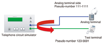
2.3.3 Test 3(1) Description We changed the facilities connecting to the upstream of the analog terminal and performed a call-originating test using a telephone circuit simulator that simulated an analog circuit (Fig. 8).
Test method: Call the pseudo-number 123-5691 that combines the numbers 1, 2, 3, 5, 6, and 9 that were found to be outside the standard from the results of test 2. (2) Results No events as in the case of GW A were observed when changing the facilities connecting to the upstream of the analog terminal and making a call in this test. 3. FindingsIn this series of tests, certain numbers called from an analog terminal connected to GW A could not be recognized, and no connection could be made to the other party. We found that the power difference between certain low/high frequency combinations of the push-button signals was not within the 5-dBm standard and that the electrical requirements of DC circuits were not satisfied. Another reason why connections could be made with GW B but not with GW A could be because specifications are different for the analog port. Specifically, power specifications for the low-/high-frequency level of push-button signals at the analog port were –9/–8 dBm for GW A and –13/–11 dBm for GW B. The fact that one GW could connect the call and the other could not may also be due to product differences in the receiving sensitivity of the push-button signals. 4. ConclusionWe reported here a case study of a problem that occurred after a switchover to a VoIP circuit. When a problem occurs, an early solution can generally be reached and a prolonged problem can be prevented by collecting configuration information and device logs at an early stage and analyzing them. Moreover, IP-system analysis techniques such as packet capture are currently necessary. However, when attempting to solve problems related to VoIP GWs used in combination with IP and legacy interfaces, we cannot solve them without the use of troubleshooting methods and measurement devices that can deal with various types of interfaces. Finally, even a failure that seems to have been solved by replacing equipment should be governed by technical criteria (rules). It is not simply a compatibility issue as commonly concluded; there is always a specific reason for the failure. |
||||