 |
|||||||||
|
|
|||||||||
|
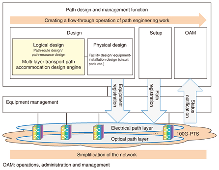
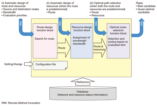
Regular Articles Vol. 14, No. 8, pp. 50–56, Aug. 2016. https://doi.org/10.53829/ntr201608ra2 Path Accommodation Design Engine for Simply and Reliably Designing Multi-layer Transport NetworksAbstractCore and metro transport networks continue to be simplified with the adoption of 100-Gbit/s packet transport systems. In line with this, the engineering work involved in path accommodation design and management is being carried out as a smooth flow, which is referred to as creating a flow-through operation. This article describes a multi-layer transport path accommodation design engine that takes into account the reliability demanded by each service in order to accommodate optical and multi-granular electrical paths from a few megabits per second to 100 Gbit/s. Keywords: PTS, optical path, multi-layer, accommodation design 1. IntroductionTo flexibly keep up with future increases in communication traffic, core and metro networks are evolving into multi-layers integrating optical and electrical paths on the 100-Gbit/s packet transport system (100G-PTS) [1]. Furthermore, to simplify networks while improving their quality, reliability, and interoperability, it is necessary not only to design networks in such a way that the closed paths in each layer of the optical-path or electrical-path layers are accommodated—which we refer to as accommodation design—but also to achieve a way to select routes that takes into consideration both path layers, the assignment of resources (i.e., wavelength and bandwidth used for paths), and the accommodation design of the optimal paths for each service on the basis of various conditions such as redundancy and reliability of routes. 2. Multi-layer transport path accommodation design engineThe multi-layer transport path accommodation design engine (hereinafter, design engine) was developed by NTT Network Innovation Laboratories and is positioned as part of a logical design function block, as shown in Fig. 1. An overview of the design engine is shown in Fig. 2. The assignment of wavelength or bandwidth and the route of optical or electrical paths are automatically designed in consideration of source and destination nodes as well as various design conditions, and the results are returned to the operator.
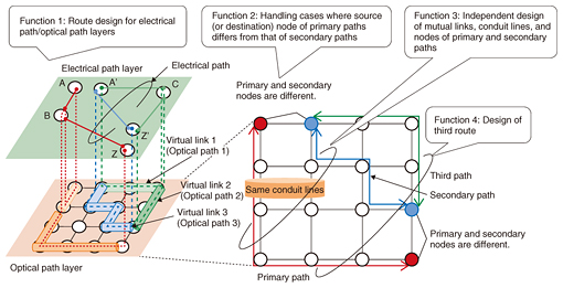
In developing the design engine, we assumed a usage scenario in which an operator handles the accommodation design of paths. The following suppositions were made regarding application scenarios involving automatic design: (i) routes and resources should be designed as a whole; (ii) routes should be designed by operators themselves, but resources should be designed automatically; (iii) routes and resources should be designed by operators themselves, but delay times and other elements should be calculated; and (iv) not only optimal design results (best matched to the design conditions) but also quasi-optimal design results (approximately matched to the design conditions) should be looked at and judged in an integrated manner. Moreover, we considered requirements such as providing designs applicable to specific design policies for each service, future expandability such as the addition of equipment and equipment vendors, and easy of embedding in network operation systems. The design engine has the following features: (1) functional partitioning based on the usage scenario; (2) multiple candidate routes in accordance with the design policy; (3) flexibility and expandability thanks to a configuration file that sets various design conditions and software startup parameters when adding other network elements and network equipment vendors; and (4) easy implementation of embedded equipment in network operation systems. These four features are first described here in terms of the entire design engine, and the primary functions and key features of the design engine are then explained. 2.1 Functional partitioning based on usage scenarioThe design engine is composed of three function blocks configured in accordance with the above-described design scenarios concerning the operator as shown in Fig. 2: a route-design function block (for calculating candidate routes from a source node to a destination node); a resource-design function block (for assigning wavelengths to optical paths and assigning bandwidth to electrical paths); and an optimal route-selection function block (for selecting routes and ranking them according to evaluation priorities). 2.2 Multiple candidate routes in accordance with design policyWhen a source node and a destination node are input, the design engine calculates optimal candidate routes and multiple quasi-optimal candidates. The multiple candidate routes are prioritized in accordance with a priority order set by means of the configuration file, ordered as optimal candidate routes and quasi-optimal candidate routes, and output as response results. This ordering of multiple candidates can be imagined as displaying multiple candidates (e.g., trains) via a transfer-information app on smartphones in accordance with a display priority set by the user in terms of elapsed time, transport charge, and number of transfers. One usage scenario is that the operator can not only select optimal candidates; the operator has the freedom to select from multiple candidates including quasi-optimal ones whenever they please. 2.3 Flexibility and expandability by a configuration fileIf the types of equipment and the equipment vendors are different, the values of parameters used for bandwidth calculations and design conditions may differ. Moreover, the design conditions may change when the equipment is modified. As for the design engine, flexibility and expandability are achieved by responding to changes in the design conditions and parameters by using the configuration file. Utilizing the path-route-design function block makes it possible to flexibly change design conditions such as the upper limit of delay times of end-to-end services and the upper limit of the number of nodes passed through. Moreover, it is possible to parameterize the evaluation priority used for ordering optimal candidates by the optimal route-selection function block using configuration files. For example, it is possible to set the order of priority such as delay times of end-to-end services and the number of nodes passed through as an evaluation priority. Setting the weighting of evaluation priority in this manner makes it possible to output optimal candidate paths in response to services and usage purpose. 2.4 Built-in easy implementation in network operation systemThe design engine is implemented on the basis of a network model, path model, and object model specified in international standard TMF513 [2]. Furthermore, it adopts RMI (Remote Method Invocation)—an API (application programming interface) generally used with Java—as an interface, and it can be easily implemented by embedding it in the network operation system. 3. Path-route-design function blockThe path-route-design function block provides integrated path designs in accordance with a variety of path-route-design conditions and the state of physical, optical, and electrical layers. To put that concretely, it makes it possible to select routes on the basis of design conditions such as the building that the system will be accommodated in, the number of nodes, links, and conduit lines for the physical layer, the delay time of paths in path layers, and the delay-time difference between paths of the currently used system and the backup system. The path-route-design function block has four primary functions, which are described below and shown in Fig. 3.
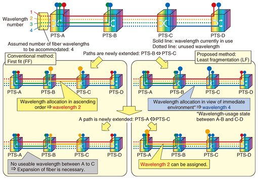
3.1 Batch design for multi-layer pathsWith multi-layers (which mediate both optical paths and electrical paths) as targets, paths are designed in batches. For this batch design, first, optical paths that can accommodate electrical paths are searched for. An optical path is deemed to be a virtual link in the electrical-path layer; a virtual link that can accommodate the bandwidth number of the electrical path is searched for, and candidate routes are selected in order of the fewest number of virtual links passed through. As for the path accommodation design for nodes A’ to Z’ in Fig. 3, candidate routes are selected in order of paths via virtual link 3 and paths via virtual links 1 and 2. In contrast to the previously described example, in cases where there are no optical paths that can accommodate electrical paths, it is possible to design multi-layers as a whole by designing an optical path afresh and designing an electrical path on the virtual links. In addition, the assignment of a wavelength for the optical path at that time is executed by calling the resource-design function block (described below). This function makes it possible to independently design routes in the respective layers for optical and electrical paths. 3.2 Design when source (destination) nodes of primary and secondary paths differPath routes can be designed even if the paths do not have the same source or destination node for a redundancy path, which consists of primary and backup paths. In this way, the case in which the currently used system and backup system of the client equipment are installed at physically separate locations (or when equipment at the same location is installed separately) can also be handled as a redundant configuration. 3.3 Independent designs for nodes, links, and conduit lines of primary and secondary pathsIt is possible to design routes that avoid duplication of transit nodes and transit links of the primary path and the secondary path. It is also possible to design routes that avoid duplication of conduit lines that contain the respective transit links of the primary path and the secondary path. 3.4 Design of third path for primary and secondary pathsReliable design that can handle changes in network configuration due to factors such as major disasters and fluctuations in the set number of nodes is possible. For example, when the existing primary or secondary path is disrupted, route design involving a third path [1] to rebuild a redundant configuration is implemented in order to avoid the disrupted points. 4. Resource-design function blockThe resource-design function block provides wavelength and bandwidth for the routes calculated by the path-route-design function block or the routes set by the operator in advance. In the design of resources for assigning wavelengths to optical paths, a wavelength-continuity constraint is imposed on the links routed; that is, the same wavelength must be used between source and destination nodes. The concept of optical paths was advocated by NTT research & development laboratories in 1992; therefore, an algorithm for carrying out path accommodation design to allocate optical-path routes and wavelengths was proposed [3]. An algorithm called least fragmentation (LF) [4], which was devised by NTT Network Innovation Laboratories, is implemented in the resource-design function block. When multiple candidate wavelengths can be assigned to candidate routes, the LF algorithm selects a single wave number that minimizes fragmentation (i.e., a state in which wavelengths utilized for certain routes are fragmented) while considering the wavelength-utilization status of adjacent links on the candidate path routes. To put that more concretely, the wavelength-utilization status of links is expressed as two values: “0” (false) for unused and “1” (true) for used. The value of an exclusive OR (XOR) between adjacent links is taken as a linear measure, and the wave number that minimizes that XOR value is selected as the wavelength to be assigned. In this manner, the wavelength allocated to candidate routes is calculated in a short time—even in the case of a large-scale network—by a simple logic operation including the candidate path route and the wavelength-utilization status of adjacent links on that path. As a conventional wavelength-assignment algorithm, the first fit (FF) algorithm (Fig. 4) for assigning wavelength in ascending order of wave number does not account for the wavelength-utilization status of adjacent links on the candidate route. Accordingly, to accommodate a new path request in the network (i.e., source node PTS-A and destination node PTS-C in Fig. 4), it is necessary to add links between nodes, for example, between nodes PTS-A and PTS-B in Fig. 4. In contrast, with the LF algorithm, the wavelength is selected so that the same wavelength can be assigned to maintain continuity for as many links as possible; consequently, new requests for paths can be accommodated in the network without having to add links in response to those requests, as shown in the example in Fig. 4.
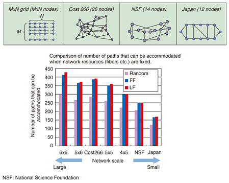
In addition to the LF and FF algorithms, a random algorithm (which randomly selects allocable wavelengths) can be used. The results of a comparative evaluation of the three algorithms—on the basis of the number of paths that can be accommodated in relation to network configuration (i.e., scale)—are shown in Fig. 5. Over the entire network scale range, the number of paths that can be accommodated is largest when the LF algorithm is used. It can thus be concluded that the LF algorithm can effectively utilize network resources to the maximize extent possible.
5. ConclusionWe developed a multi-layer transport path accommodation design engine that achieves optimal path design and satisfies the required conditions for various services. From here on, we will continue to research and develop technologies for optical-path accommodation design while aiming to create core and metro networks for economically providing a multitude of broadband services. References
|
|||||||||


