 |
|||||||||||||||
|
|
|||||||||||||||
|
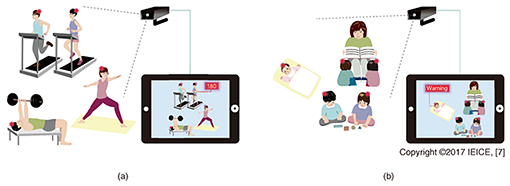
Regular Articles Vol. 15, No. 7, pp. 36–40, July 2017. https://doi.org/10.53829/ntr201707ra1 Heart Rate Measurement with Video Camera Based on Visible Light CommunicationAbstractWe have developed a system based on optical camera communication and an encoding method that can transfer the heart rates (HRs) of multiple people with high precision. The system can potentially measure and transfer the HRs of hundreds of people with their positional information. The unique system is composed of HR sensor units and a conventional camera. It is presented here along with the novel event timing encoding method. Keywords: visible light communication, heart rate, event timing encoding 1. IntroductionRecent advances in light emitting diodes (LEDs) have opened up numerous possibilities for new visible light communication (VLC) technologies and systems [1]. VLC systems typically use LEDs and photodiodes. However, much progress has also been made recently in image sensor technology. Consequently, optical camera communication (OCC), a VLC system that uses LEDs and image sensors, has been attracting a lot of attention. A typical OCC system is composed of a single camera with multiple sensors distributed in sight of the camera [2]. OCC is advantageous in that it can obtain data from multiple points together with the sensor positions. From another point of view, as the population of elderly citizens increases, healthcare monitoring is becoming an important and promising application. For example, suppose a situation where a member of a gym is wearing a heart rate (HR) sensor that transmits his or her heart beat (HB) in real time (Fig. 1(a)). The gym staff could provide immediate aid to the member if they observed danger signs in the member’s HR [3]. This technology will also be beneficial for small children and infants. One potential application is monitoring the HRs of sleeping infants in child care centers (Fig. 1(b)). Monitoring their HRs would enable a caregiver to quickly deal with abrupt HR changes such as those associated with sudden infant death syndrome [4].
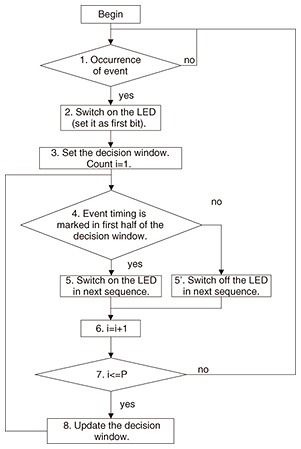
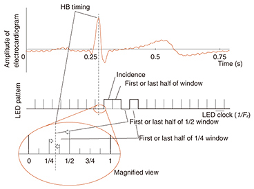
However, with the conventional radio frequency wireless network, this task is not as easy as one may think. The network may not work well if there are a large number of devices [5] and positional information is difficult to obtain. Therefore, we have developed an OCC system [6] and an event timing encoding (ET encoding) technique [7] that can precisely transfer the intervals of HB events with a conventional camera. The high spatial directionality of visible light enables multiple data channels to be transmitted simultaneously through different optical paths along with the positional information of sensors. In addition, OCC can potentially be combined with natural image analysis in the future. 2. Method to transfer precise HB timingAs explained in the introduction, the system is composed of a sensor unit and camera (image sensor). The capturing speed of a commonly used camera is usually limited to 30 or 60 frames per second, which is not high enough to observe the event timing of the HB. Furthermore, the system only detects the ‘on/off’ state of the LED for simplicity and robust processing. If someone simply flashes the LED at a sensor unit when an HB event occurs, the captured images on the camera side give us only 33 ms of time resolution. However, the requirement is less than 4-ms resolution even for simple HR analysis. ET encoding is designed to overcome this problem. The idea is that it first signalizes the occurrence of the HB event and then refines the relative timing with consecutive LED patterns. In practice, the unit simulates the frame rate of the camera and switches the LED ‘on’ and ‘off’ using this clock (LED clock). When the unit detects an HB event, it marks the timing location of the event within this LED clock frame. The unit first sends an ‘on’ signal after the detection to inform the decoder of the LED clock frame. When the camera detects this first ‘on’ signal, we can determine on the camera side that the event occurred somewhere in the previous frame shot. The unit continuously sends details about the location of the event in the LED clock frame. From these data, we can refine the timing of the event. In other words, ET encoding tells the LED clock frame that the event is occurring and sends the natural binary expression of the event timing in the frame. The flow chart for sending the event timing by flashing an LED is shown in Fig. 2. The encoding image is shown in Fig. 3.
The time resolution of the HB interval in ET encoding is calculated as
where Tmin is the shortest term of the HB interval and Fz is the capturing speed of the camera (which is the same as the flashing frequency of the LED). This ET encoding is more efficient than directly transferring the HB time interval under the condition of
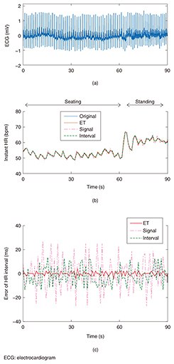
where Tmax is the longest term of the HB interval. 3. Demonstration and comparisonThe ET encoding was implemented in our HR monitoring system. The unit was custom-built and can be attached to “hitoe” sensing fabric developed by Toray Industries, Inc. and NTT. It samples an electrocardiogram signal with 500 Hz and 10 bits of resolution. A microcomputer installed in the unit searches for the HB timing and utilizes 5 bits (five on/off flashes of an LED) to send one HB interval. A comparison between the HR observed from direct monitoring and the HR decoded from the LED flashing patterns captured by the camera is shown in Fig. 4. HB intervals were calculated for HRs obtained by using four different methods: an HR extracted from the original waveform; an HR transferred by the interval encoding method; an HR reconstructed using an event signal (the same as using only the first signal in ET encoding); and an HR decoded from ET encoding. When 5 bits of data were transferred from the unit, ET encoding gave an almost identical HR.
4. Future developmentThis article explained efficient encoding methods that can be used in OCC with a low-frame-rate image sensor. We introduced ET encoding, which sends the rough timing of the HB in the first signal and refines its location. Theoretically, ET encoding can send the HR with better resolution than directly sending the interval data in many cases. We implemented ET encoding in a custom-made electrocardiogram sensor. The results showed that ET encoding transferred HRs with higher resolution when the same bit/beat was used. Concerns that the visible light might be irritating to the human eye can be allayed by using a near-infrared LED. This system will be implemented in the future to obtain HR data and will be particularly useful for evaluating health risks. Since the system utilizes a common camera, it can be combined with natural image analysis. In addition, data transferrable by ET encoding are not limited to HR. Other data such as spikes in neuronal activity can also be transferred by ET encoding. Further research will open up new possibilities of OCC. References
|
|||||||||||||||


