 |
|||||||||
|
|
|||||||||
|
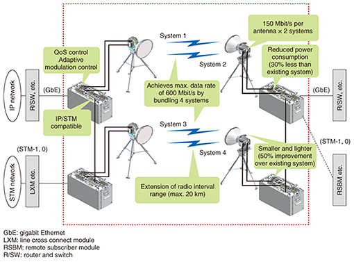
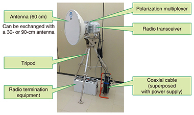
Feature Articles: Terrestrial Wireless Systems for Disaster Recovery to Provide Customer Relief Vol. 16, No. 1, pp. 42–46, Jan. 2018. https://doi.org/10.53829/ntr201801fa6 Portable Digital Wireless System for Disaster Recovery with Long-range Operation and Compact/Lightweight ConfigurationAbstractNTT Access Network Service Systems Laboratories has developed a portable digital wireless system for disaster recovery (11/15P-150M-N). This system optimizes gain allocation in the antenna and radio transceiver to achieve a maximum improvement of 30% in radio-interval range while reducing weight and volume by approximately 50% each compared to the existing system. If damage occurs to transmission paths in regions where reliability-maintenance schemes such as looping are difficult, this system enables prompt disaster relief using a 156-Mbit/s or 52-Mbit/s synchronous digital hierarchy interface or Ethernet interface. Keywords: disaster recovery, wireless system, relay transmission paths 1. Portable digital wireless system unequaled in the worldAs a provider of diverse telecommunication services, NTT has developed and deployed various types of wireless systems for disaster recovery. The aim here has been to achieve prompt relief or restoration of damaged landlines and transmission paths (severed optical cables, damaged conduits, fallen bridges, etc.) that occur as a result of an earthquake, flood, volcanic eruption, fire, or other disaster [1, 2]. Recent years, however, have seen a high incidence of disasters such as the Great East Japan Earthquake inflicting massive damage to communication facilities, and in the wake of these disasters, radio-based systems for disaster recovery have become all the more important [3]. The existing wireless system for disaster recovery targeting relay transmission paths can restore a digital transmission path with a 156-Mbit/s or 52-Mbit/s synchronous digital hierarchy (SDH) interface. However, the rapid growth in Internet protocol (IP) networks has made the restoration of transmission paths between communication equipment having an Ethernet interface essential. In addition, there are cases in which the transmission path between NTT communication buildings cannot be restored using the existing wireless system for disaster recovery because of the long distance between buildings. Against this background, the 11/15P-150M-N system was developed to enable the restoration of IP networks and to extend the range of the radio interval for disaster relief. To achieve restoration of IP networks, the system features a maximum radio transmission capacity of 600 Mbit/s—four times that of the existing system—and incorporates a quality of service (QoS) function and an adaptive modulation function. It also features a maximum radio transmission distance between termination equipment of 20 km. Furthermore, the total weight of a complete set of equipment is approximately 80 kg. The manually transportable system consists of an antenna, radio transceiver, polarization multiplexer, coaxial cable, radio termination equipment, and tripod. The portability of this digital wireless system used for relay transmission paths is a feature unequaled in the world. It enables prompt recovery of relay transmission paths on a synchronous transfer mode (STM) or IP network anytime and anywhere even if telecommunication facilities are damaged. The configuration and features of this wireless system are shown in Fig. 1.
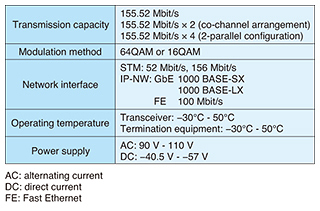
2. System overviewThis is a digital wireless system transmitting digital signals at a bit rate of 156 Mbit/s per system on the 11-GHz or 15-GHz radio frequency band using 64 quadrature amplitude modulation (QAM), or 16QAM. In addition, connecting system equipment in parallel enables system bundling in a 156 Mbit/s × 4 manner for a maximum digital-signal data rate of 600 Mbit/s. The main specifications are listed in Table 1, and a photograph of the equipment is shown in Fig. 2.
3. Key features of systemThe effectiveness of the system is due to its four key features described here. 3.1 Extended range and compact/lightweight configuration by optimizing gain allocationIf range could be extended while maintaining the quality of the radio circuit, it would be possible to restore a long transmission path that could not be restored using the existing system. To achieve this, it would be necessary to increase the gain of the system, but this would also substantially increase the weight of the equipment and antenna, thereby undermining system portability. To secure the desired radio-circuit quality, it was decided to optimize the gain allocated to the antenna and radio transceiver, making it possible to extend the transmission range to a maximum of 20 km (compared to 15 km maximum with the existing system) without sacrificing portability. In addition, the total volume and weight were both reduced by approximately 50% compared to the existing system. 3.2 Implementation of Ethernet interface and provision of QoS functionThe new system has an SDH interface (156 Mbit/s and 52 Mbit/s) as used in the existing system, but it also mounts an Ethernet interface (gigabit Ethernet and Fast Ethernet) to enable connection to IP networks; whichever interface is used is selected at the time of operation. When the Ethernet interface is used, the system performs priority control by identifying passing IP packets and distribution control according to the state of radio circuits. It incorporates a four-class QoS function to prevent the loss of high-priority packets and uses adaptive modulation technology to change the transmission capacity according to the propagation conditions. With these features, the system can provide optimized radio transmission quality and enable interoperability with Ethernet networks. 3.3 Improved spectrum efficiency and greater capacity through multi-value QAMThe new system adopts 64QAM, which is currently the mainstream modulation method for fixed microwave radio systems. This feature achieves a two-fold improvement in spectrum efficiency compared with the existing system. It can also increase transmission capacity by two times the existing value when using a pair of parabolic antennas in a co-channel arrangement* and by four times (600 Mbit/s) when using two pairs of parabolic antennas in a parallel setup. 3.4 Improved workability and safetySystem workability has been greatly improved by superposing two transmit/receive interface signals and the power supply on a single coaxial cable, whereas the existing system requires three cables. Moreover, because the assembly of the radio transceiver, antenna, polarization multiplexer, and tripod entails high-elevation work on the platform of a steel tower on top of an NTT communication building, all screws used in the assembly have been given an anti-dropping mechanism. In short, the screws have a structure that takes safety into consideration by preventing them from falling to the ground. Moreover, the assembly can be done using only one hexagonal wrench. As a result of these measures, assembly and installation work that required four to five workers and took about 1 hour with the existing system can now be performed with just two to three workers in about 20 minutes.
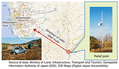
4. Deployment status and usage scenariosThe system was first introduced in 2013 by NTT EAST and NTT WEST and is gradually being deployed throughout Japan. This system can be used in various scenarios: (1) for prompt response to a damaged relay transmission path between NTT communication buildings (including those caused by damaged conduits, fallen bridges, severed submarine cable due to contact with a ship, and severed cable due to an automobile accident); (2) for construction of redundant transmission paths in the event of a disaster in mountainous areas and on islands where construction work is difficult; (3) for provision of a transmission path as a temporary backup when refurbishing submarine cables or upgrading fixed digital microwave facilities; and (4) for construction of temporary transmission paths for public events in mountainous areas and on islands or for seasonal purposes. The system has already been used for emergency restoration of facilities following a landslide on Izu-Oshima island caused by typhoon No. 26 in 2013 (Fig. 3) and after a severed submarine cable caused by a typhoon that made landfall in Hokkaido in 2016. Additionally, to provide for the possible occurrence of a disruption or accident at the G7 Ise-Shima Summit in 2016, the system was installed on the roofs of several key NTT communication buildings, thereby improving the reliability of telecommunications.
References
|
|||||||||


