|
|||
|
|
|||
       |
Practical Field Information about Telecommunication Technologies Vol. 16, No. 2, pp. 61–66, Feb. 2018. https://doi.org/10.53829/ntr201802pf1 Gas Leak Search Techniques for Underground Metallic CablesAbstractGas leaks that occur in underground metallic cables can potentially cause circuit problems that disrupt communications. This article describes the techniques used to identify gas leaks in underground cables. This is the forty-fourth article in a series on telecommunication technologies. This contribution is from the Access Engineering Group, Technical Assistance and Support Center, Maintenance and Service Operations Department, Network Business Headquarters, NTT EAST. Keywords: gas leak, metallic cable, underground cable
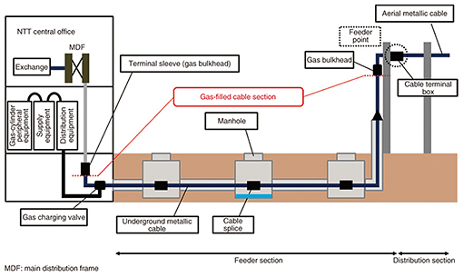
1. IntroductionUnderground cables that have been laid throughout Japan are found in underground conduits and manholes, and in such environments, countermeasures must be taken to prevent damage caused by rainwater and groundwater. In particular, because the core wires of metallic cables are made of copper, the penetration of water into the cable or a cable splice can cause circuit faults, and measures are therefore taken to prevent such water penetration. With subscriber metallic cables, the interval from the NTT central office to the feeder point is called the feeder section and that from the feeder point to the customer premises is called the distribution section. In the feeder section interval, the cable interior is filled with dry air to create sufficient pressure to prevent the penetration of water (Fig. 1).
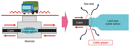
In gas-filled cables, the occurrence of a gas leak will cause the gas pressure within the cable to drop, thereby increasing the risk of water penetration. It is therefore important to monitor the gas pressure and take appropriate measures. 2. Gas leak factorsOne factor in gas leaks is cable movement (creeping phenomenon) in which a cable moves from its original position due to temperature-related elongation/contraction, vibrations caused by passing vehicles, and other factors. A gas leak can occur if excessive force comes to be applied to the cable gripper at a cable splice due to cable movement (Fig. 2). Creeping can also damage the cable jacket and create pinholes that can also be a factor in gas leaks. Places with a soft foundation where heavy vehicles tend to pass and straight roads with a notably uneven surface constitute environments in which cable creeping can easily occur.
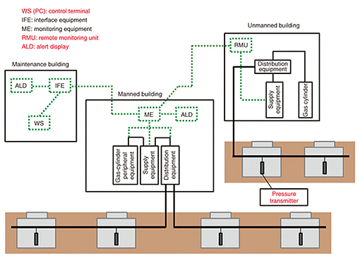
3. Inference of gas leak pointsA system has been deployed that can remotely monitor the gas pressure within underground metallic cables. This remote gas monitoring system includes a pressure transmitter that converts gas pressure within cables to electrical signals, a remote monitoring unit (RMU) that receives data from a pressure transmitter, an alert display (ALD) that displays alerts, and a workstation (WS) or personal computer (PC) that displays data (Fig. 3).
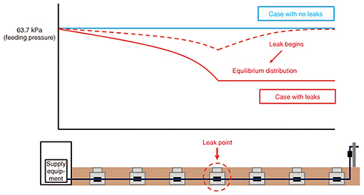
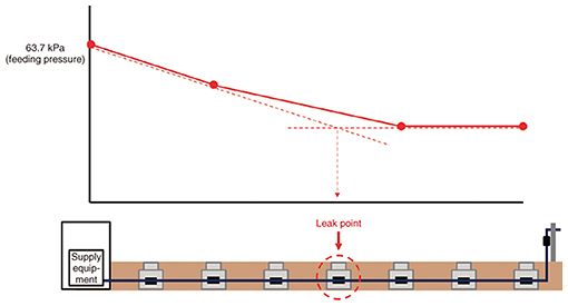
In this system, a pressure transmitter capable of measuring gas pressure is installed at each cable connection point. This makes it possible to remotely measure and tabulate gas pressure within the cable and to use this data to prepare a pressure distribution chart. If there is no gas leak in the cable, the plot on the pressure distribution chart will be flat. However, if a gas leak is present, a drop in pressure can be seen originating at the leak location. Then, after a certain amount of time, if there is no change in the size of the gas leak hole or in the gas feeding pressure, the result will be an equilibrium distribution in which the distribution of pressure applied to the terminal side from the leak point is invariable (Fig. 4).
The gas leak point is inferred by analyzing the pressure distribution chart using pressure measurement values at a minimum of four points. Here, given that the pressure distribution chart indicates a state of equilibrium distribution, the leak point is inferred to be the intersection of the straight line on the gas-feeding side and the straight line on the terminal side (Fig. 5).
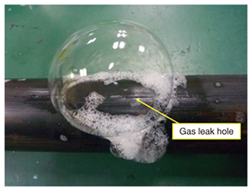
4. Introduction to gas leak search technology(1) Gas leak search using soapy water A leak hole can be promptly searched for if the result of the above gas leak point inference method indicates that a manhole is the suspected location of a leak. Once a maintenance personnel is inside the manhole, he/she coats the surface of the cable or connection point with soapy water or similar, and if a leak hole does in fact exist, it will be revealed by the formation of soapy-water bubbles as the gas leaks out (Fig. 6).
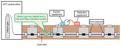
A search with soapy water is relatively easy to do, but variations of this technique and its results can easily occur between maintenance personnel, depending on the concentration of the soapy water and the ease of coating the target material, which raises concerns that some leaks may be missed. (2) Gas leak search using helium gas If a leak hole is not found with soapy water after conducting a leak search inside all manholes concerned by inferring gas leak points, or if a location other than a manhole or handhole (e.g., within a conduit interval) turns out to be the suspected location, a leak search can be conducted using helium gas. Helium gas has a number of advantageous properties; it is non-combustible and odorless, has a high degree of dryness (does not degrade the electrical insulation of cable core wires), and does not react with other substances. In short, it is chemically stable while being much lighter than air (mass ratio: 1:0.17). Furthermore, its presence in the atmosphere is extremely low, which makes it useful as a tracer gas. Moreover, it is not environmentally destructive, nor is it harmful to the human body. In a helium gas search, the dry air in a cable is replaced with helium gas. Then a search for a helium gas leak is carried out using helium gas detection equipment. In preparation for this search, a stopcock is used to close the duct outlet of the conduit suspected of being the leak location. If a gas leak hole exists within this conduit, the helium gas leaking from the hole will fill the closed conduit. The air in the conduit is sucked out using suction equipment and then examined by the detection equipment. The existence of a leak hole within the conduit can therefore be checked based on the presence or absence of helium gas (Fig. 7).
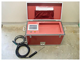
A gas leak search using helium gas requires replacing the dry air within the cable with helium gas and using specialized search equipment, making it more complex than the soapy water technique (Fig. 8). However, it is a more reliable method of finding leaks than the soapy water search method.
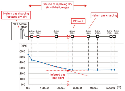
5. Process of gas leak searchWe describe here an example process of searching for a gas leak in an underground metallic cable. First, the gas leak point is inferred based on the gas pressure distribution chart obtained by the gas remote monitoring system. In this process, the suspected leak location is established based on the gradients of the gas pressure plots and the terminal pressure. If the inferred leak point is inside a manhole, the cable or connection point can be coated with soapy water to search for a location where soapy-water bubbles form. At this time, gas leaks at the cable gripper of a connection point will be carefully checked since such leaks have a high probability of occurring there. If a gas-pressure-drop alert should be displayed, the cable can be charged with clean gas (from a cylinder) from the terminal side to increase gas pressure as an emergency measure, but this may make it difficult to correctly grasp the gas pressure distribution. It is important to take note of the gas pressure distribution at the time of a gas pressure drop and compare it with the gas pressure distribution after charging with clean gas from the terminal side. When a leak hole cannot be found using soapy water despite conducting a leak search in all manholes concerned based on the results of the gas leak point inference method, or if the suspected leak location is within a conduit interval, a leak search will then be performed using helium gas. Before the search is conducted, the duct outlet of the conduit enclosing the suspected leak location will be closed using a stopcock. To replace the dry air in the cable with helium gas, the cable will be charged with helium gas from the NTT central office gas room via points preceding the suspected leak location. To facilitate the replacement of dry air with helium gas at this time, the dry air within the cable will be blown out via a gas valve at the connection point on the other side of the helium gas charging point corresponding to the suspected leak location. Once the dry air within the cable has been sufficiently replaced with helium gas, the air within the closed-off conduit is sucked out by suction equipment and passed to helium gas detection equipment to check for the presence of helium gas within the conduit. If the cable within this conduit does indeed have a leak hole, helium gas will be detected at this time (Fig. 9).
6. ConclusionThis article introduced techniques used to search for gas leak points in underground metallic cables as a preventive measure against circuit faults. The Technical Assistance and Support Center is committed to using the knowledge and experience it has gained in the maintenance and operation of diverse facilities to respond to requests for technology consultations and support from all concerned parties and to promote technology dissemination with the aim of improving the reliability of access facilities. |
||