|
|||
|
|
|||
       |
Practical Field Information about Telecommunication Technologies Vol. 16, No. 8, pp. 73–78, Aug. 2018. https://doi.org/10.53829/ntr201808pf1 Case Study of Problem in Multifunction Telephones Connected to a Business Phone SystemAbstractThis article describes a non-activation problem that was occurring in customer’s multifunction telephones connected to a business telephone system and the investigation that was carried out to determine the cause. This is the forty-seventh article in a series on telecommunication technologies. Keywords: business phone, multifunction telephone, characteristic impedance
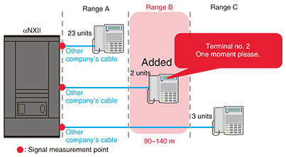
1. IntroductionWhen a customer added multifunction telephones to NTT’s αNXII business phone system, the added terminals failed to activate (called a non-activation problem). There were no past examples of this problem, and since it was possible that it would occur again in the future, we investigated this problem and conducted tests to determine the cause of the fault. In this article, we describe the investigation of the fault, the results of analysis, and countermeasures. 2. Fault overviewThe equipment configuration is illustrated in Fig. 1. As shown, multifunction telephones are connected to NTT’s αNXII business phone system, with 23 phones connected in range A, 2 in range B, and 3 in range C. A star wiring scheme is used to connect all of these multifunction telephones using existing cables manufactured by another company.
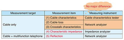
The 23 multifunction telephones in range A and the 3 in range C were all determined to be operating normally. However, it was found that the 2 multifunction telephones in range B were displaying the message “One moment please” and were failing to activate. On-site maintenance personnel replaced the other company’s cables that were connecting the non-activated multifunction telephones with NTT cables. As a result, the two terminals were activated, and the fault was resolved. 3. Investigation of causeAlthough the telephones had been activated, we carried out an investigation to determine what caused the fault and prevent future occurrences. 3.1 Investigation 1 (evaluation of cable characteristics)Here, we describe the system components that were investigated and explain the results. 3.1.1 Measurement itemsGiven that the fault was resolved by on-site maintenance, we focused our attention on the two types of cables used and evaluated their characteristics. The components that were measured are listed in Table 1 and described below.
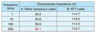
Evaluated cables: A: Other company’s cable (110 m) B: NTT cable (110 m) The measurements were conducted using the business phone’s signal frequency of 250 kHz. (1) Cable characteristics (cable only) (2) Cable loss (cable only) (3) Crosstalk characteristics (cable only) (4) Characteristic impedance*1 (cable only) (5) Reflection*2 (cable + multifunction telephone) 3.1.2 Investigation resultsNo major difference was found in these two types of cables for items (1) to (3) above. The characteristic impedance (item (4)) of the cable measured at the business phone’s signal frequency of 250 kHz was approximately 85 Ω for cable A, the other company’s cable, and 110 Ω for cable B, NTT cable, a difference of about 25 Ω. These measurement results are listed in Table 2.
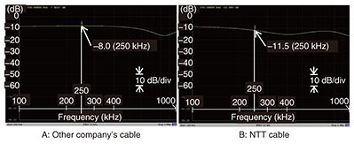
The results of measuring the amount of reflection (item (5)) when connecting a multifunction telephone at 250 kHz were –8.0 dB for cable A and –11.5 dB for cable B, a difference of 3.5 dB. The measurement results are shown in Fig. 2.
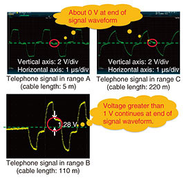
3.1.3 DiscussionThe impedance of the NTT cable was 110 Ω, which satisfies the business-phone operating conditions of 110±20 Ω, but the impedance of the other company’s cable was 85 Ω, which does not satisfy the conditions. Furthermore, on examining the reflection when connecting a multifunction telephone, we found that the reflection of the other company’s cable was found to be 3.5 dB greater than that of the NTT cable, so it could be considered that this reflection was affecting the signal. 3.2 Investigation 2 (effect of reflected wave)3.2.1 Measurement itemsThis problem occurred in multifunction telephones that were connected with another company’s cable and when the telephones were installed within a certain distance from the business phone system. We therefore focused our testing on how the signal waveform differed between the normal-operation time and the non-activated time. We set up equipment at the Technical Assistance and Support Center using the same configuration as that in Fig. 1 and measured the various components at the measurement points indicated by “ 3.2.2 Investigation resultsThe results of measuring signal waveforms (for ranges A, B, and C) by oscilloscope are shown in Fig. 3. When we examine the portion within the red circle for each range, we can see that the voltage of the waveform was about 0 V for normal operation in ranges A and C and greater than 1 V at the non-activated time in range B.
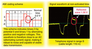
3.2.3 DiscussionThe αNXII business phone uses the Alternate Mark Inversion (AMI) coding scheme. If the voltage at the end of the signal waveform within the red circle is greater than 1 V, the signal cannot be read as normal data (Fig. 4). The above results show that this voltage was about 0 V in ranges A and C, indicating normal operation. In range B, however, a voltage of 1.28 V (reflected wave) occurred due to the reflected-wave effect, with the result that the terminal could not recognize the signal normally and could not be activated.
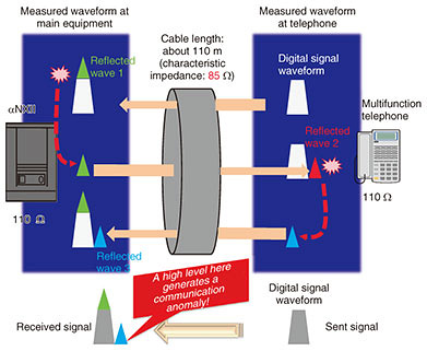
4. Inference of cause of faultThe test results presented above indicate that the characteristic impedance of the other company’s cable used for equipment wiring was 85 Ω, which does not satisfy the characteristic impedance of the business phone system used here (110±20 Ω). Consequently, when a multifunction telephone was connected to this type of cable, there was large signal reflection, which affected the signal within a certain range of cable length. We inferred from these results that the fault was caused by a breakdown in the signal transmitted by the multifunction telephone. The breakdown was due to the impedance mismatch in the other company’s cable, which prevented the main equipment from correctly reading the signal. The fault generation mechanism is depicted in Fig. 5.
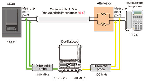
In range A, voltage greater than 1 V at the end of the signal waveform does not continue, and although a reflected wave exists, the reflection duration is short, so there is little impact on the signal. Likewise, in range C, voltage greater than 1 V at the end of the signal waveform does not continue. This can be explained by considering that while a reflected wave exists, the cable length is long, which has the effect of attenuating the signal itself as well as the reflected wave. The effect of the reflected wave on the signal is consequently small. 5. CountermeasuresTwo possible countermeasures were considered: a) Replace with an NTT cable Effect: Achieves impedance matching between the terminal and cable, suppresses reflected waves, and activates the terminal normally. b) Insert a countermeasure device (attenuator) Effect: Attenuates the reflected wave and activates the terminal normally. Although countermeasure a) was implemented effectively in the initial investigation, as described in section 2, we considered that it may not always be possible to use this countermeasure and thus implemented countermeasure b). We therefore prepared and tested an attenuator at the Technical Assistance and Support Center. 5.1 Test methodWe inserted an attenuator (resistance) in a 110-m length of the other company’s cable and checked the effect of reducing the voltage level in the reflected wave (Fig. 6).
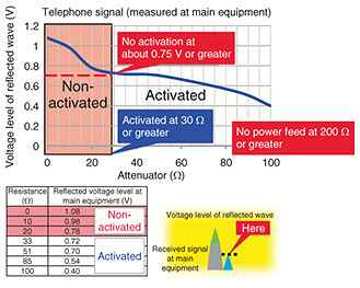
5.2 Test resultsThe test results are shown in Fig. 7. The following conclusions were made based on these results.
We found based on the above results that setting resistance in the range of 30–100 Ω would work well as a countermeasure to this fault. 6. ConclusionIn this article, we introduced a problem in multifunction telephones connected to NTT’s αNXII business phone system handled by the Technical Assistance and Support Center. As shown by this case study, it is important that the cable used between business phone equipment (main equipment and terminal) be impedance-matched with the business phone system. The EMC Engineering Group of the Technical Assistance and Support Center aims to achieve prompt resolution of noise faults related to conduction and radiation and to contribute to the smooth provision of communication services. To this end, it is proactively engaged in technology dissemination activities through technical collaboration, technology development, and technical seminars. |
||