|
|||
|
|
|||
       |
Practical Field Information about Telecommunication Technologies Vol. 17, No. 4, pp. 31–35, Apr. 2019. https://doi.org/10.53829/ntr201904pf1 Introduction of Salt-damage MapsAbstractOutdoor communication facilities are exposed to damaging weather and climate conditions and therefore require regular inspection and maintenance to ensure they operate safely and reliably. Such facilities also need to be placed in the optimum locations to reduce the potential damage from the exposure while best supporting telecommunication services. This article describes a map developed by the Technical Assistance and Support Center that illustrates the degree of damage from salt in different areas of Japan. This is the fifty-first article in a series on telecommunication technologies. Keywords: salt damage, steel pole, corrosion
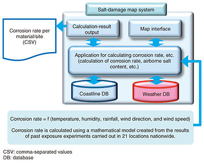
1. IntroductionOutdoor communication facilities are constantly subjected to the effects of the weather in various natural environments, and they are therefore at risk of deteriorating. Materials such as metals, concrete, and plastics are used for communication facilities, with metals being widely used for overhead structure supporting equipment such as suspension lines and metal fittings. Metal deteriorates due to corrosion in the form of rusting. Since such corrosion involves thinning of the metal, it greatly reduces the structural strength of the metal and may lead to serious facility failures and accidents. Accordingly, it is necessary to take appropriate measures such as confirming the amount of deterioration by inspection and implementing remedial measures. Salt is known to be the main factor causing corrosion outdoors. It gets scattered on the land in the form of fine sea-salt particles carried on the wind blowing from over the sea. Although the concentration of scattered salt is low inland, the coastline is a salt-damage environment in which metals are easily corroded. Salt damage can be expressed in the form of a map (salt-damage map, hereafter) that illustrates the degree of salt damage in a certain environment. The Material Engineering Group of NTT EAST Technical Assistance and Support Center is investigating the cause of specific failures of communication facilities caused by various kinds of deterioration and striving to prevent the recurrence of such failures by applying our expertise. In this report, we introduce a salt-damage map as an approach to countering corrosion deterioration of communication facilities. 2. Overview of salt-damage mapsThe salt-damage map system provided by the former NTT Energy and Environment Systems Laboratories to NTT EAST in 2011 is configured as shown in Fig. 1.
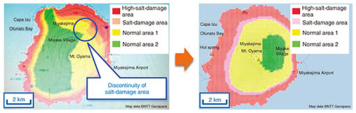
This system has a function for calculating the zinc corrosion rate at an arbitrary point and displaying it on a map. The calculation is based on the relationship between the corrosion rate and the distance from the coast and weather conditions modeled using the results of exposure experiments on galvanized steel (used as a corrosion countermeasure for communication facilities) that were conducted at 21 points nationwide by the Technical Assistance and Support Center since the era of the Nippon Telegraph and Telephone Public Corporation (the former NTT). The corrosion rate of zinc plating is calculated using a mathematical model into which weather data such as temperature, humidity, and distance from the coast are input. To calculate the corrosion rate, weather data for the last 50 years or so (since 1969) collected by weather observation stations operated by the Meteorological Agency are used, and weather conditions supplemented by the weighted averages, that is, data weighted in regard to three weather observation stations located nearest to the point to be calculated, are applied. With the display interval taken as 100, 200, and 400 m for distances from the coast of up to 2 km, 2 to 4 km, and 4 to 5 km, respectively, the corrosion rate of zinc at a height 6 m from the ground is calculated and output as a result. 3. Refinement of salt-damage map using latest weather dataThe weather observation stations providing the weather data used in a conventional salt-damage map are placed in about 200 locations and scattered at distances of more than 15 km on average; consequently, the weather data complemented by the weighted average for the three nearest weather observation stations contained large errors. In recent years, due to the development of meteorological technology, weather data throughout Japan can be obtained as a 1-km mesh. It was thus possible to refine the salt-damage map by recalculating it using weather data for 10 years beginning in 2007 (Fig. 2).
4. Plans to utilize the new salt-damage mapThe salt-damage maps are expected to be useful in carrying out both engineering work and maintenance, as described in this section. 4.1 Engineering workThe application area of steel poles has been expanded in line with a revision to the application of concrete poles for single utility poles that was carried out in June 2017. In areas where concern about salt damage is high, steel poles completely coated in resin (known as uncorrodible (UC) steel poles) are used. The application area of UC steel poles is determined based on the existing facilities and past corrosion deterioration; however, the placement of these poles often varies depending on the people deciding where to put them. The use of the salt-damage map to determine the application area of UC steel poles is an effective way to solve this problem. For example, rather than determining the application area by defining the area within 1-km or less from the coast as the salt-damage area, applying quantitative data and past findings will make it possible to determine the area according to the actual corrosion rate at the site (Fig. 3). As a result, it is possible to reduce the risk of mistakenly applying steel poles for general areas in salt-damage areas or applying UC steel poles in general areas.
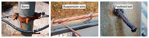
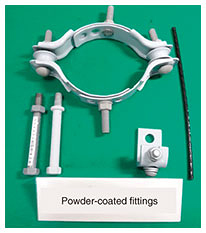
Moreover, as for compensation for pole-relocation work, determination of the application area of UC steel poles affects the calculation of compensation for the relocation; accordingly, it is sometimes desirable to utilize a salt-damage map so that the application area can be determined more carefully. 4.2 Maintenance workIn areas of high salt concentration, zinc-plated overhead metal fittings may corrode about 10 years after installation and reach the level for renewal (Fig. 4). In these high-salt-damage areas, powder-coated metal fittings are effective as countermeasures against corrosion (Fig. 5). Powder coating is a method of coating an object with a powdery paint without using a solvent, and it has been used since 2005 as an anticorrosion paint for ground-level and underground steel poles.
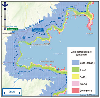
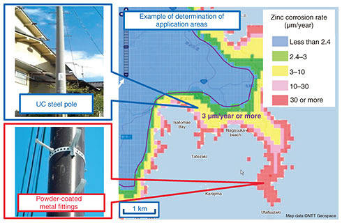
An example of determining the application areas of corrosion-resistant facilities and fittings using salt-damage maps is shown in Fig. 6. The region where zinc corrosion is 3 μm/year or more indicates where UC steel poles would be placed, and the region where zinc corrosion is 30 μm/year or more (high-salt-damage area) indicates where powder-coated fittings would be used. The areas with high salt damage that require such countermeasures may be known empirically by some people doing the actual work who are familiar with local circumstances. However, introducing the salt-damage map makes it possible to identify such areas more clearly and reliably without any omissions.
5. Implementation of trials to introduce new salt-damage mapsA trial utilizing salt-damage maps as part of a weather database for maintenance bases of access facilities is currently underway. After the results of the trial are confirmed, we plan to incorporate the new salt-damage maps as a function of the weather database in NTT’s company-wide system. Moreover, we want to make it available to practitioners of telecommunication construction companies so that they can utilize the maps in various scenarios such as construction and management of facilities. 6. Concluding remarksA new kind of salt-damage map that enables determination of application areas for corrosion-resistant fittings and facilities was introduced. The conventional way of determining salt-damaged areas involves the use of empirical judgment based on the corrosion situation of actual facilities and uniform judgment based on the distance from the coast. In future, it is recommended to use salt-damage maps in a comprehensive manner so that they can support proper introduction of corrosion-resistant fittings. At the Technical Assistance and Support Center, we will continue to develop the salt-damage maps described in this report while also working on maps to visualize areas such as those affected by lightning damage and strong winds. From now onwards, we will continue to disseminate these maps as part of a weather database that will support the construction and operation of communication facilities, and we urge all stakeholders to take full advantage of that database. |
||