|
|||||||||||||||||||
|
|
|||||||||||||||||||
       |
Regular Articles Vol. 17, No. 5, pp. 40–44, May 2019. https://doi.org/10.53829/ntr201905ra1 Recent Progress in Applications of Optical Multimode Devices Using Planar Lightwave CircuitsAbstractThe optical propagation mode—the electromagnetic field distribution of light propagating through a waveguide—is attracting attention as a new degree of freedom of light and is expected to provide new functions and improved optical characteristics in optical devices and systems. In this article, we introduce optical device technologies that utilize the optical propagation mode in an integrated optical waveguide component called a planar lightwave circuit. Keywords: multimode, waveguide, PLC
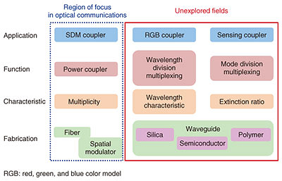
1. IntroductionIn optical communications, the degrees of freedom of light such as its intensity, wavelength, phase, and polarization have been used for multiplexing and higher-order modulation [1]. In an optical waveguide, the optical field propagates in specific distribution patterns called modes. Single-mode transmission with only the fundamental mode has mainly been used in optical communications. In recent years, however, large-capacity transmission using mode multiplexing has been reported [2]. This is called spatial division multiplexing (SDM) because it uses the degree of freedom of the spatial optical field distribution. Optical propagation modes are also expected to be utilized for the next generation of technology for optical signal processing and sensing, as well as for SDM transmission. For stable optical performance, optical communications systems are generally composed of devices for single-mode transmission, which include a light source, modulator, and multiplexer. Therefore, an important component to handle the modes is a mode converter (MC) that can convert the fundamental mode and higher-order modes. A technology map of MCs is shown in Fig. 1. There are MCs using optical fiber, spatial modulators such as liquid crystal on silicon, and waveguides. Since mode utilization has been limited to SDM transmission, the focus has mainly been on signal multiplexing. For other functions such as wavelength multiplexing and sensing, precise mode conversion is necessary.
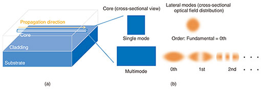
We are now researching silica planar lightwave circuit (PLC) technology and various devices using it as a means of controlling modes. In this article, we introduce a wavelength division multiplexer using optical propagation modes and an ultralow-crosstalk MC for an optical time domain reflectometer (OTDR). 2. Structure of optical multimode waveguideA PLC is a waveguide circuit composed of a silica core and cladding on a substrate such as Si (silicon) or SiO2 (silicon dioxide), as shown in Fig. 2(a). A waveguide pattern is fabricated using standard wafer processes such as photolithography and reactive ion etching. The core structure of single-mode and multimode waveguides is shown in Fig. 2(b); the intensity of optical field distribution with several modes is also shown in a cross-sectional view. The core width and height of the single-mode waveguide enable only the fundamental mode to exist in a lateral direction. The intensity of the optical field distribution is shown at the upper right of Fig. 2(b). A multimode waveguide has a core size in which first or higher-order modes can coexist with the fundamental mode. The number of modes that can exist is determined by the core size.
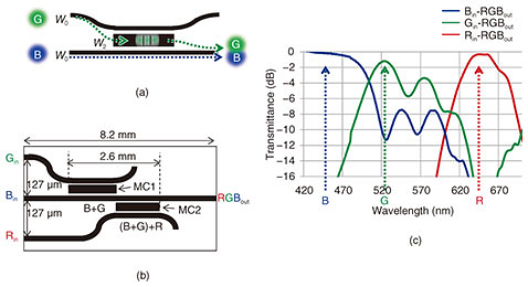
The intensity of optical field distribution is shown at the lower right of Fig. 2(b). In the waveguide, the mode should be precisely controlled for various applications by changing the width of the core, since the characteristics change when the modes propagating through the waveguide change. PLC technology could be the most promising approach for providing such highly accurate fabrication of waveguides, since it has been developed for application to optical communications for many years [3]. In the following sections, we introduce several applications using multimode PLC technology. 3. RGB couplerA compact red (R)-green (G)-blue (B) multiplexer for laser diodes is attractive for use in glass-based displays, head-mounted displays, and compact projectors. Such laser imaging applications use multiple laser sources and multiplex them into a single beam that is then scanned onto a screen by a beam scanner such as a microelectromechanical system mirror. RGB multiplexers have conventionally been constructed by using mirror prisms, multilayer films, and optical fibers. An RGB multiplexer (RGB coupler) based on a PLC is promising for downsizing to a single chip integrating the functions used in a conventional RGB multiplexer [4, 5]. An RGB coupler typically uses directional couplers (DCs) to multiplex light with different wavelengths. The wavelength dependence of the coupling length is used to implement the wavelength multiplexing function because the higher the wavelength is, the shorter the coupling length becomes. For example, a DC structure is designed to match the coupling length of blue light and the recoupling length of green light. Then the blue and green lights are multiplexed by the DC. It is difficult to multiplex more than three wavelengths this way, and even in the case of two wavelengths, the DC tends to become long due to the need for period-matching between the coupling and recoupling. To solve this problem, we developed an RGB coupler using MCs, each of which includes an additional multimode waveguide that is wider than the single-mode waveguides. The added multimode waveguide is sandwiched between the single-mode waveguides of a conventional DC, as shown in Fig. 3(a), where the black line represents the core of the optical circuit. The additional multimode waveguide works as an MC that converts between 0th-order and higher-order modes. Because the MC converts only wavelengths satisfying the conversion conditions, it is possible to selectively multiplex desired wavelengths. For example, when the MC is designed to satisfy the conversion conditions at the green wavelength, the green light can move to the next single-mode waveguide by means of mode conversion. In contrast, almost all the blue light goes through the MC, as shown in Fig. 3(a). Since this coupling structure can multiplex green and blue light as if it were wavelength-independent thanks to suppression of the transition of unwanted-wavelength light, the coupler length does not need to be the lowest common multiple of the coupling lengths of the colors. As a result, the coupler can be shorter than conventional DCs. Our RGB coupler using MCs is shown in Fig. 3(b). Because MC1 and MC2 were designed to satisfy the coupling conditions at the green and red wavelengths, the coupler can multiplex R, G, and B into the same waveguide. The total length of MC1 and MC2 is 2.6 mm, which is less than half as long as the conventional RGB coupler using DCs. The measurement results for the RGB coupler fabricated using PLC technology is shown in Fig. 3(c). The transmittances are −0.3 dB for blue, −1.2 dB for green, and −0.3 dB for red. Although the transmittance of green light is relatively low, the results confirmed that we succeeded in making a very small RGB coupler with low loss (better than 1.5 dB) using MCs.
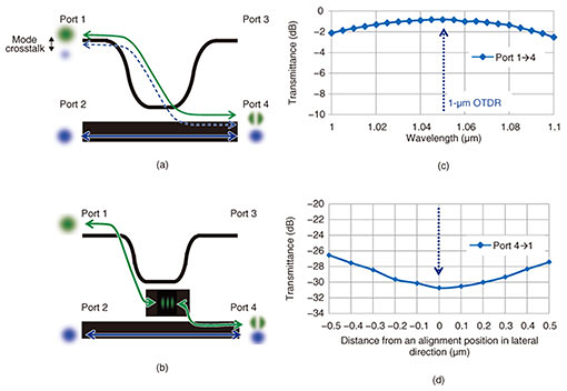
4. Sensing coupler for sensitive OTDRAn OTDR is used to diagnose optical fiber links. A 1-μm-band mode-detection OTDR (1-μm OTDR) system has been reported [6, 7] that uses 1-μm-band probe pulses to generate not only the fundamental mode but also the first-order mode as backscattered light in typical single-mode fibers compliant with ITU-T G.652*. A mode coupler is used to separate the backscattered light into individual modes and to select the mode of the probe pulses. The first-order mode at the wavelength in the 1-μm band is more sensitive to trouble spots in optical fiber links, such as macro/micro-bends, than the fundamental mode in the communications wavelength band. Therefore, the 1-μm OTDR is very promising for finding potential trouble points before they have a serious impact on an optical communications system. The 1-μm OTDR requires an MC with low mode crosstalk to ensure sensitive detection. Here, we introduce a mode coupler that achieves high conversion efficiency and low mode crosstalk by using a multistage mode conversion method. A schematic of the structure and operation of a conventional mode coupler is shown in Fig. 4(a). The input fundamental mode from port 1 is converted to the first-order mode and output from port 4. Almost all of the fundamental mode from port 2 passes through the coupler. The fundamental mode and first-order mode are generated as backscattered light. The fundamental mode and first-order mode from port 4 can be detected separately from the mode-mixed light at ports 1 and 2. The dashed line shows the mode crosstalk path. Part of the fundamental mode from port 4 is coupled to the thin waveguide with the fundamental mode and output from port 1 as a noise component. To solve this noise component problem, we developed a coupler with high conversion efficiency and low mode crosstalk, as shown in Fig. 4(b). An additional mode conversion waveguide placed between the single-mode waveguide and multimode waveguide of the mode coupler indirectly converts the mode into a desired one via an intermediate mode. In this work, we chose the second-order mode as the intermediate mode. Adding the second-order mode enhances the mode isolation and reduces mode crosstalk. Setting the waveguide width correctly ensures that no additional loss occurs due to adding the waveguide. The measured conversion efficiency of the coupler fabricated using PLC technology is plotted in Fig. 4(c). The conversion efficiency is −0.8 dB at the wavelength of 1.05 μm, which is used for the 1-μm OTDR. The measured mode crosstalk is shown in Fig. 4(d). The mode crosstalk is under –30 dB. These results confirm that we succeeded in making a mode coupler with high conversion efficiency and low mode crosstalk by using a multistage mode conversion method.
5. Future prospectsThis article introduced optical multimode devices that use PLC technology. We showed that by using the mode as a new degree of freedom of light, we can miniaturize waveguide devices and achieve high performance. Establishing design, manufacturing, and evaluation technologies for handling modes will pave the way for the implementation of unprecedented optical devices with new functions and unique properties. References
|
||||||||||||||||||