|
|||||||
|
|
|||||||
       |
Feature Articles: Smart Infrastructure Facility Management Vol. 19, No. 1, pp. 56–61, Jan. 2021. https://doi.org/10.53829/ntr202101fa9 High-precision Management of 3D Location Information of Underground Facilities by Using High-precision 3D Geospatial InformationAbstractBy enabling the management of underground facilities with high-precision three-dimensional (3D) location information, the Smart Infra Platform was developed by NTT Infrastructure Network Corporation (NTT InfraNet) to improve the efficiency of facility-management operations, such as improving the efficiency of inquiries about facilities and reducing the number of on-site observations during construction. However, most underground facilities are managed with drawings created during the design of the facilities; thus, facility-location information is not provided. To provide geospatial information for underground facilities, it is necessary to create high-precision 3D geospatial information that represents the real world with high precision then identify the location of the underground facilities and give accurate 3D location coordinates Keywords: high-precision 3D geospatial information, geospatial information, Smart Infra Platform
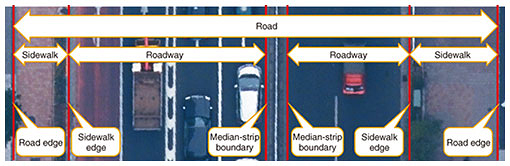
1. Issues concerning underground facility management and the Smart Infra Platform1.1 Issues concerning management of underground facilitiesCurrently, underground facilities are managed with plan and cross-sectional views, and those views are stored in the form of drawings created during facility design. Most of such information is generated by converting computer-aided design (CAD) drawings to image data, which do not contain geospatial information indicating the burial location. A road-ledger map is generally used as a background map showing the location of facilities. However, it is difficult to accurately identify the location of facilities due to changes to, for example, the current road layout from that when the facilities were designed. During construction work, it is therefore necessary to bring the drawings to the construction site, where the maintenance personnel of the infrastructure company can compare the drawings with the site to determine the location at which the underground facility is buried. To identify the location of underground facilities in this manner, it is necessary to use the experience and expertise of skilled people to estimate the burial location on a facility-by-facility basis. To respond to the shortage of experienced maintenance personnel and further improve operational efficiency, it is necessary to improve the conventional means of managing underground facilities through digital transformation (DX). As a first step in this DX, it is necessary to manage the location of underground facilities in the real world with high accuracy. 1.2 Underground facilities on the Smart Infra PlatformThe Smart Infra Platform manages the locations of underground facilities with computer-computable three-dimensional (3D) geospatial information, namely, latitude, longitude, and altitude, which mark burial locations in the real world. It uses the 3D geospatial information of underground facilities, excavation areas, and depth information to determine the presence of underground facilities and the impact of the excavation on nearby facilities in that 3D space. It is also possible to reduce the operational burden on on-site maintenance personnel by converting the highly accurate location information on underground facilities into a format that can be represented in virtual reality and mixed reality. Accordingly, the 3D geospatial information on underground facilities must have a strong positional correlation with the real world. The tolerance error between the location of real-world underground facilities and that of managed underground facilities is expressed using the map-information level, an index that indicates map-representation accuracy of numerical topographic map data and average total accuracy of the data inside the numerical topographic map. Underground facilities managed using the Smart Infra Platform has a map-information level of 500, the error (accuracy) of which is within a standard deviation of the horizontal position of 0.25 m and standard deviation of the elevation point of 0.25 m. This accuracy is similar to the positional accuracy of the road-ledger map, and it is sufficient to determine the relative position of not only underground communication facilities but also other underground facilities such as of electricity, gas, and water and sewage. However, current underground facilities are managed via drawings without location information; therefore, a site must be surveyed to incorporate highly accurate location information having a map-information level of 500. This survey is prohibitively costly as well as being unrealistic because the site has to be excavated. To solve this problem, NTT Infrastructure Network Corporation (NTT InfraNet) is developing a location standard and high-precision 3D geospatial information to ensure drawings of underground facilities have high positional accuracy with a map-information level of 500. 1.3 High-precision underground facility management using high-precision 3D geospatial informationHigh-precision 3D geospatial information consists of high-precision location and altitude data of manholes in roads, road boundaries, and entrances and exits to underground facilities in the real world (Fig. 1). The reason that high-precision 3D geospatial information consists of such pieces of information is because they are easy to measure using aerial photographs and a mobile mapping system (MMS) because they are exposed on the ground surface in the real world, and these locations cannot be easily changed (i.e., they stay at the same location for a long time). By creating high-precision 3D geospatial information from aerial photographs and an MMS that satisfies the map-information level of 500, the original positional accuracy is improved through the creation of high-precision 3D geospatial information with this map-information level. Using manholes and road boundaries in this high-precision 3D geospatial information as a positional reference and by aligning the position of the manholes and road boundaries in the drawings of underground facilities, it is possible to incorporate highly accurate location information and altitude into the drawings. Moreover, if underground facilities already have coordinates as geospatial information, by selecting data with the appropriate shape and size for the type of underground facilities from the high-precision 3D geospatial information of manholes and by matching the facilities that are closest, it is possible to provide highly accurate position and altitude information on underground telecommunication facilities.
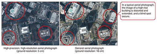
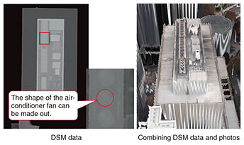
2. Creation of high-precision 3D geospatial information2.1 Means of creating high-precision 3D geospatial informationTo create high-precision 3D geospatial information, it is first necessary to survey the real world with high precision. Unlike general surveying, it is necessary to measure a wide area, so measurement can be roughly classified into two types. One type involves surveying with high-resolution and high-precision aerial photographs. Such photographs are suitable for initial data development because the data-acquisition cost is determined by the capturing area regardless of the length of the road to be measured. However, it is impossible to survey sections that cannot be photographed, such as under overpasses and railways. Therefore, it is impossible to create high-precision 3D geospatial information for such sections. The other measurement type involves using an MMS for surveying. Since an MMS involves measuring an area from a roadway using laser scanners or stereo cameras mounted on vehicles, it is possible to acquire data on areas below overpasses; however, it may not be possible to acquire data on sections of sidewalks that cannot be seen from the roadway. Moreover, the data-acquisition cost depends on the road length, so it is necessary to narrow the number of roads from which data are to be acquired, and an MMS is suitable for data acquisition for maintenance operations. In our latest case at NTT InfraNet, we used high-resolution, high-precision aerial photographs for the initial development of high-precision 3D geospatial information on the 23 wards that make up central Tokyo. 2.2 Creation of high-precision 3D geospatial information using high-precision, high-resolution aerial photographsHigh-precision, high-resolution aerial photography does not allow for ortho-processing (distortion correction) based on a conventional digital elevation model (DEM)*1. Instead, it is used to construct a high-precision and high-definition digital surface model (DSM)*2 and carry out geometric-correction processing of captured image data with the DSM. An aerial photograph taken in this manner is called a true ortho (i.e., a perfect orthographic image), and unlike conventional aerial photographs, it is not affected by the distortion of high-rise buildings, so it is easier to obtain the location and shape of ground structures (Fig. 2). In such an aerial photograph, 5 cm on the ground is treated as one data unit, so highly accurate location information and altitude can be obtained. Its resolution is high enough to show the detailed shape of above-ground structures such as an air-conditioner fan installed on the roof of a building (Fig. 3).
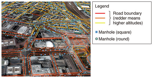
High-precision 3D geospatial information with a map-information level of 500 can be created by stereo-drawing the shapes of road boundaries, manholes, and entrances and exits to underground facilities by using high-precision, high-resolution aerial photographs (Fig. 4).
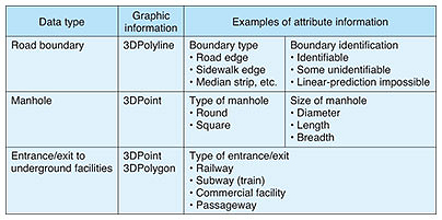
2.3 Data structure of high-precision 3D geospatial informationHigh-precision 3D geospatial information is defined in Environmental Systems Research Institute, Inc. (ESRI)’s shapefiles, and the data structure differs according to data type such as road boundaries, manholes, and entrances and exits to underground facilities. The graphic information is defined as a 3D graphic, and the information used for aligning underground facilities is defined as attribute information. Road-boundary data are used to align underground facilities, such as gas pipes, which are located by offsetting the distance from the road boundary. Therefore, boundary-type and boundary-identification attributes are used to select the appropriate data for alignment. Manholes are used to align underground facilities with exposed facilities above ground, such as for telecommunications, electricity, and water and sewage services. Manhole-shape and -size attributes are therefore used to select the appropriate data for alignment (Table 1).
The management identifier and date of data creation/update for managing high-precision 3D geospatial information as well as identification information for high-precision, high-resolution aerial photographs referred to when creating high-precision 3D geospatial information are defined as common attribute information. Such information is used for future maintenance of high-precision 3D geospatial information. The advantage of choosing ESRI’s shapefiles is that the specifications are open. As a result, data can be easily exchanged with other systems and converted to formats such as GeoJSON (geospatial data interchange format based on JavaScript Object Notation), which is widely used in open-source systems, and DXF (Drawing Exchange Format) and DWG (Drawing), which are used in architectural CAD.
3. Future of high-precision 3D geospatial informationNTT InfraNet is currently creating high-precision 3D geospatial information of the 23 wards of central Tokyo, and it is scheduled to be completed by the end of November 2020. We then plan to expand its development to ordinance-designated cities by the end of FY2021. For this expansion, we are aiming to further improve the efficiency of the maintenance of high-precision 3D geospatial information. We are currently verifying technologies using artificial intelligence (AI), including the automation of manhole detection, automatic road determination, and automatic boundary extraction from high-precision, high-resolution aerial photographs. AI makes it possible to not only reduce the cost of data creation for high-precision 3D geospatial information but also shorten the period for data maintenance, which will make the similarity of the data with the real world more reliable. Although we are currently using a data-creation method that uses high-precision, high-resolution aerial photographs, we are considering using another data-creation method that uses an MMS to take into account data maintenance. The ultimate goal of developing high-precision 3D geospatial information is not only to identify the location of underground communication facilities but also all underground facilities owned by electricity, gas, and water/sewage companies and share that information with them. If underground facilities of all companies had high-precision location and altitude based on high-precision 3D geospatial information, the location of underground facilities could be handled in common by all those companies. As a result, facilities management and maintenance carried out by individual companies can be integrated, and that integration will lead to the implementation of smart maintenance, i.e., efficiently and effectively manage facilities through DX.
Authors (from left): Tomoki Suizu, Assistant Manager, Smart Infra Promotion Department, NTT InfraNet; Shigeru Chiba, Manager, Smart Infra Promotion Department, NTT InfraNet; and Akihiko Minamino, Manager, Smart Infra Promotion Department, NTT InfraNet |
||||||