|
|||||||
|
|
|||||||
       |
Practical Field Information about Telecommunication Technologies Vol. 19, No. 4, pp. 58–62, Apr. 2021. https://doi.org/10.53829/ntr202104pf1 Novel Tool for Finding a Defective Field-assembly Connector in the FieldAbstractThis article introduces a novel tool for finding defective field-assembly connectors just after service personnel assembled them in the field. The tool uses multi-wavelength loss profiles to identify the defective connectors. This is the sixty-third article in a series on telecommunication technologies. Keywords: field-assembly connector, FTTH, insertion loss
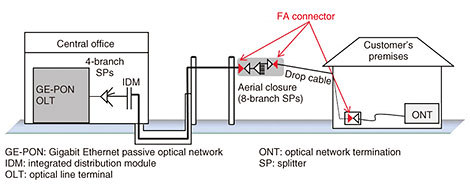
1. IntroductionConfiguration of fiber-to-the-home (FTTH) service equipment is illustrated in Fig. 1. Field-assembly (FA) connectors are commonly used at each connection point in closures on utility poles and in customer’s premises. In comparison with fusion-splice and mechanical splice connectors, FA connectors have the advantages of prompter opening of services and easier switching work. However, owing to incorrect procedures during assembly of the connectors or insufficient maintenance of tools, the quality of connection in an FA connector might deteriorate soon after installation.
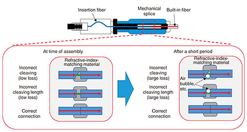
The Technical Assistance and Support Center (TASC), NTT EAST, is continuously working to solve problems with various communication equipment. This article presents a novel maintenance tool using multi-wavelength loss profiles to find failures of FA connectors. 2. Reduce early failures of FA connectorsIn accordance with previous investigations of failure cases and verifications based on reproductions of such failures, early failures of FA connectors have been found to occur due to incorrect procedures during connector-assembly work or insufficient maintenance of tools such as fiber cleavers [1]. The insertion-loss-generation mechanism [2] due to incorrect assembly of FA connectors is shown in Fig. 2. In the case of a correct connection, the insertion fiber and built-in fiber are butt-connected in the mechanical splice section without leaving any gaps. However, in the case of a defective connection, a minute gap forms at the butt joint due to incorrect fiber cleaving or incorrect cleaving length. In such a case, significant insertion loss due to the gap may not occur immediately after assembly because the gap is filled with a refractive-index-matching material. However, if air bubbles mixed in the material move, for example, due to temperature variations, and reach the point at which the communication light passes through the gap, large insertion loss will occur. As we described above, defective FA connectors may cause early failure.
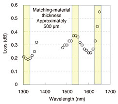
As countermeasures against the above issues, we previously devised and developed tools that call attention to these issues during connector assembly. These tools include a fiber-cleaving checker, for checking the cleaved surface of the insertion fiber, and a pocket manual that lists key points during installation. While these tools have helped decrease the number of failures of FA connectors, early failure has not been eradicated. Therefore, we developed an FA connector checker that can easily determine defective connectors on the spot as a further countermeasure. 3. FA connector checker3.1 Principle of the FA connector checkerThe difference between a correct connector and defective connector is the presence or absence of a refractive-index-matching material on the path along which communication light passes. Accordingly, our FA connector checker finds a defective FA connector using the multiple wavelength characteristics on the refractive-index-matching material. We investigated insertion losses of correct and defective connectors in regard to each wavelength. Figure 3 shows the insertion losses of the refractive-index-matching material at each wavelength. We found that the insertion losses of the refractive-index-matching material depend on the wavelength of the light traveling through it. We also found that the insertion losses of the correct connector varied little, but those of the defective connector varied significantly in each wavelength. These findings indicate the FA connector checker can identify hidden defective connectors by comparing the insertion losses at multiple wavelengths.
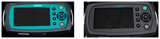
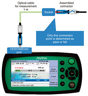
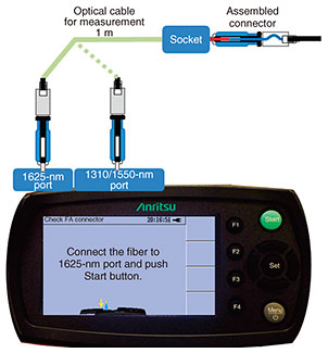
3.2 Investigation on installing the checker in a multi-wavelength optical-time-domain reflectometerWith an emphasis on portability and workability so that workers can easily determine defective connectors on site, we installed our FA connector checker in a multi-wavelength optical-time-domain reflectometer (OTDR). There are two types of compact OTDRs generally available: two wavelength (1310/1550 nm) and three wavelength (1310/1550/1625 nm). On selecting the type of OTDR under the assumption of actual field use, it is necessary to consider factors such as detection accuracy, operability, and price. Accordingly, we evaluated the accuracy of two- and three-wavelength prototypes of our FA connector checker in an experimental environment. One hundred FA connectors were fabricated, and connectors with variations in insertion losses immediately after fabrication and connectors with loss fluctuations of 3 dB or more during the temperature-cycling test were selected. From comparing the detection accuracies of the two- and three-wavelength checkers, we found that accuracy was 96% for the former and 100% for the latter. Although the accuracy of the three-wavelength checker was higher, both checkers were satisfactory. 3.3 Physical details of the prototypesPhotographs of the prototypes are shown in Fig. 4. These prototypes were respectively installed in two MT9090A OTDRs (two- and three-wavelength types) manufactured by Anritsu. Either of the two- or three-wavelength-type prototypes can be mounted in the MT9090A without changing its size. The difference in the two prototype checkers is that the two-wavelength one can measure two wavelengths via one port, but the three-wavelength one is divided into a 1310/1550-nm port and 1625-nm port.
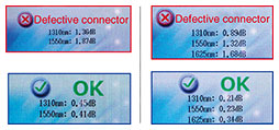
3.4 Procedure for determining defective connectorThe procedure for determining a defective connector using our checker is explained as follows. Our checker can be used on the spot where the FA connector is installed such as on utility poles or in customer’s premises, as shown in Fig. 1. A defective connector can be identified simply by connecting the checker to the connector with an optical cable for measurement. Regarding the two-wavelength prototype checker, when the Start button is pressed, the insertion losses at two wavelengths (1310 and 1550 nm) are measured for 30 seconds each, then “pass” or “fail” is automatically displayed (Fig. 5). For the three-wavelength-type prototype checker, the user is given guidance prompting them to switch to the 1625-nm port after measurement at the two wavelengths (1310 and 1550 nm) have been completed (Fig. 6), and when the insertion loss at a wavelength of 1625 nm is measured, pass or fail is displayed (Fig. 7). These results indicate that the prototype checkers can automatically detect a defective connector without the need for the operator to analyze the measurements. Comparing their operation times, we clarified that the pass/fail result was displayed with the prototype two-wavelength-type checker in about one minute and with the prototype three-wavelength-type checker (including time to switch the ports) in about two minutes.
4. Summary and future workWe presented a novel FA connector checker for finding defective FA connectors and fabricated two prototypes of the checker, i.e., two- and three-wavelength. Although the two-wavelength-type checker has advantages in terms of workability (because it is not necessary to reconnect the measurement ports) and price expected from the configuration of its components, the three-wavelength-type checker has an advantage in terms of higher detection accuracy. In the future, we will investigate the advantages of both types through actual on-site trials aiming at their early commercialization. 5. ConclusionWe described our efforts in preventing early failures of FA connectors. Currently, measurements using OTDRs or power meters cannot identify a defective connector unless a significant insertion loss occurs. However, using our FA connector checker makes it possible to identify hidden defective connectors. We believe that this detection capability will greatly contribute to reducing early failures and improving the quality of service provided to our customers. At TASC, we will continue to improve the reliability of telecommunication equipment and reduce telecommunication failures on the basis of our accumulated knowledge and experience as well as new technologies. References
|
||||||