 |
|||||||||
|
|
|||||||||
|
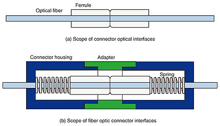
Global Standardization Activities Vol. 19, No. 6, pp. 104–109, June 2021. https://doi.org/10.53829/ntr202106gls Recent Standardization Activities of Optical Connectors in IECAbstractOptical communication networks and datacenters worldwide use a huge number of optical connectors made in many countries. Optical connectors are products that require precise components because a dimensional error of only 1 μm can affect the optical signal quality. To ensure the compatibility of connectors, it is essential to internationally standardize the component shapes, connector performance, and the measurement methods for testing them. This article introduces the standardization activities and recent trends in optical connectors. Keywords: optical connector, international standard, optical communication 1. IntroductionInternational standards for optical connectors are developed by the International Electrotechnical Commission (IEC). The IEC was established in 1906 to promote international cooperation and communication on standardization and related matters in the field of electrical and electronic technology. The work related to the development of the standard is carried out by the technical committee (TC) and subcommittee (SC) established under it, and the standardization for optical connectors is discussed in TC 86 (Fibre optics)/SC 86B (Fibre optic interconnecting devices and passive components). As of February 2021, SC 86B published the second largest number of documents in IEC after TC 61 (Household appliance safety), and the second largest number of documents in work after TC 82 (Photovoltaic power generation). Optical connector standardization activities are one of the most active in IEC. In the field of optical connectors, the single-fiber coupling (SC) connector and multi-fiber push-on (MPO) connector developed by NTT have held the top share of the market for more than 30 years. In March 2021, both connectors received IEEE Milestone*1 certification [1]. Japan has also made a significant contribution to the standardization of optical connectors and has served as the secretariat of SC 86B since 2003. IEC TC 86/SC 86B consists of three working groups (WGs), and standardization documents related to optical connectors are deliberated by WG 4 (Standard tests and measurement methods for fibre optic interconnecting devices and passive components) and WG 6 (Standards and specifications for fibre optic interconnecting devices and related components). Although the International Telecommunication Union - Telecommunication Standardization Sector (ITU-T) specifies the performance of optical connectors from the viewpoint of system requirements for communication networks, IEC documents and ITU-T documents are standardized in cooperation to prevent them from becoming double standards. The IEC standards for optical connectors are divided into four document series, as shown in Table 1: basic test and measurement procedures, performance standard, fiber optic connector interfaces, and connector optical interfaces. Figure 1 shows the specification scopes of the connector optical interfaces and fiber optic connector interfaces standards. Optical connectors connect optical fibers by aligning and adhering the fiber cores. This connection method is called physical contact (PC) connection. An alignment part called a ferrule*2 is used to align the fiber cores, and the connector optical interfaces standard specifies the dimensions of the ferrule necessary for the fiber cores to adhere to each other. The connector housings and an adapter are rigidly coupled when the connectors are connected, and the ferrules are pressed against each other using a spring built into the housing. The fiber optic connector interfaces standard defines the dimensions and spring force of the housing required for this coupling of connector housings and an adapter. Though PC connection and this coupling structure are adopted in almost all optical connectors, they are independent technologies. For example, the same SC connector requires different ferrules for single-mode optical fiber (SMF) and multimode optical fiber (MMF). The same ferrule is used for different optical connectors such as SC and FC*3 connectors. Considering the actual products, IEC standardized the PC connection and coupling structure separately as the connector optical interfaces and fiber optic connector interfaces standards, respectively.
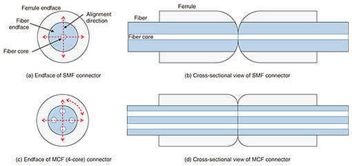
2. Trends in standardization of optical connectorsSC and Lucent (LC) connectors, which are used for connecting single-core fibers in buildings, have been widely used for connecting long-distance transmission optical fiber cables and transmission equipment. MPO connectors, which are multi-core connectors, have been extensively used for high-speed communication wiring connecting information-processing equipment in datacenters. Outdoor use of optical connectors is also becoming widespread for connecting wireless antennas to fiber optic cables. The communication capacity of SMF, which has supported high-speed and large-capacity communication for a long time, will reach its limit in the 2020s. The research and development of optical fiber for space division multiplexing (SDM), which is expected to enable large-capacity transmission over SMF, has recently been conducted. In the standardization of optical connectors, a new standardization was proposed for use in datacenters and outdoors, and activities related to the standardization of optical fibers for SDM are ongoing. 2.1 Trends in standardization of test and measurement proceduresThe standardization of measuring methods of connection loss and return loss has been promoted since 2020 for optical connectors of multi-core optical fiber (MCF), which is one of optical fibers for SDM. Figure 2 shows the SMF and MCF connector endfaces and their cross sectional views when connected. Since the optical connector for SMF has a fiber core at the center of the connector endface, the center axis of the connector is aligned only horizontally and vertically to reduce connection loss. On the other hand, MCF has a fiber core at the periphery, so the rotational direction must be adjusted. In optical connectors, the endfaces of the connectors are pressed against each other using a spring, and the fiber core adheres to ensure a sufficient amount of return loss. Connection loss and return loss are important optical characteristics that affect optical signal quality, but the farther the fiber core is from the center, the more precise rotational alignment and larger spring force are required to ensure sufficient signal quality. For this reason, it is important to evaluate the connection loss and return loss of optical connectors for MCF when deciding the core configuration of MCF. NTT aims to standardize optical fibers, optical cables, and optical connectors for SDM, but is promoting the standardization of these two measuring methods first.
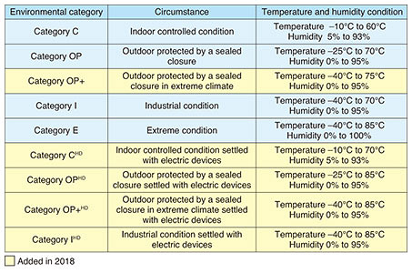
2.2 Trends in standardization of performance standardsThe performance standard for optical connectors specifies optical characteristics, such as connection loss and wavelength characteristics, mechanical characteristics, such as tensile resistance and impact resistance, and environmental resistance to temperature and humidity in the installation environment. High-speed wireless devices, such as mobile antennas and wireless local area networks, have recently been installed outdoors, and demand for optical connectors with environmental resistance for outdoor use is increasing. Table 2 lists the environmental categories in the IEC optical connector standardization revised in 2018. Before the revision, there were four categories, but the category OP+, which assumes outdoor installation in a more severe climate environment, and CHD, OPHD, OP+HD, and IHD, which assume electric parts as heat sources in each environment have been added, now totalling nine categories. Optical connectors had generally been used indoors, so most of the performance standard adopted the environmental conditions of category C. However, from 2020, the new standardization work of connector performance with the environmental conditions of category OP+HD, which is the highest temperature, started.
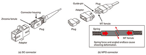
2.3 Trends in standardization of fiber optic connector interfacesThe fiber optic connector interfaces standard mainly specifies the coupling structure of the connector plug and connector adapter and the spring force that presses the ferrule endfaces against each other. Figure 3 shows the coupling mechanisms of an SC and MPO connectors. With the recent increase in speed of communication wiring in datacenters, the standards with more fiber cores than the conventional 12 cores have been actively standardized for MPO connectors. As mentioned above, optical connectors require physical contact between fiber cores to ensure a sufficient amount of return loss, and a larger spring force is required as the number of fiber cores in the MPO connector increases. Since the MPO connector has an angled endface, if the spring force is increased, a shear force is generated, the alignment of the fiber core deviates, and connection loss deteriorates. Therefore, the number of cores required for each application and the optical characteristics that can be achieved are taken into consideration, and the standardization is carried out by dividing documents into 16 cores, 24 cores, and 32 cores. Twenty-four cores and 32 cores were enacted in 2017 and 2019, and 16 cores are expected to be enacted in 2022. In addition, standardization work for 36 cores is scheduled to begin in 2021.
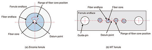
2.4 Trends in standardization of connector optical interfacesThe connector optical interfaces standard mainly specifies the position of the fiber core relative to the alignment datum of the ferrule. Figure 4 shows the endface of the zirconia ferrule used in an endface SC connector and mechanical transferable (MT) ferrule used in the MPO connector. Zirconia ferrules use a component called a split sleeve to align the outer diameter of the ferrule to the same position, thus defining the range of the fiber core relative to the ferrule center. Since the MT ferrule is aligned by inserting a guide pin into two guide holes, the fiber core position is defined by the midpoint of the line connecting the two guide hole centers. The connector optical interfaces standard defines those for standard connectors used in ordinary optical communications and those for reference connectors used for high-precision connection measurement of optical connectors. As the use of MPO connectors in datacenters has recently expanded, the number of connector suppliers has increased, and it has become necessary to accurately measure the loss of MPO connectors. MPO reference connectors are not currently standardized, so IEC started to establish new optical compatibility standards for MPO reference connectors in 2019. In theory, the maximum error in the fiber core position for the MT ferrule for the reference connector should be less than 1 μm, but since this error exceeds the measurement accuracy of the current fiber core position, there is no measurement method to confirm this even if it is specified. Therefore, NTT proposed a method for ferrule specification using fiber hole position with higher measurement accuracy and connector selection through a connection loss test.
3. Future outlookThe increasing use of optical wiring in datacenters and high-speed wireless devices and efforts to standardize optical connectors for multi-fiber and outdoor use are expected to continue. In the future, optical wiring is expected to be used on substrates in information equipment and inside automobiles in place of the conventional metal wiring to further speed up information processing, so the standardization of a higher density optical connector and improved environmental resistance optical connector will become important. In optical communications applications, the standardization of optical connectors for connecting SDM transmission fibers is expected to advance due to the development of SDM transmission technology and the progress of its standardization at ITU-T. Reference
|
|||||||||


