 |
|||||||||
|
|
|||||||||
|
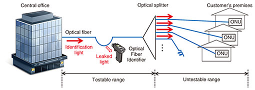
Regular Articles Vol. 19, No. 8, pp. 46–51, Aug. 2021. https://doi.org/10.53829/ntr202108ra2 Local Light Injection and Detection Technology for Optical-fiber IdentificationAbstractWe developed local light injection and detection technology that enables us to identify the target fiber below an optical splitter. This technology uses the basic characteristic of optical fibers of an optical signal propagating through the optical fiber leaks at fiber bends. This article gives an overview of this technology. Keywords: fiber identification, PON, ONU 1. Cable installation work for open up fiber-to-the-home servicesIn 2021, the total number of fiber-to-the-home (FTTH) subscribers reached about 22 million for NTT EAST and NTT WEST in Japan. FTTH services have become an indispensable social infrastructure. For telecommunications carriers to continue to provide optical communication services with high quality and stability to their customers, it will become increasingly important to maintain the construction quality of optical fiber networks and improve the efficiency of maintenance operations. The most common construction work in optical fiber networks is to open the communication lines, which connects the optical fiber installed from the central office to the optical network unit (ONU) installed in the customer’s premises. To achieve this connection, the target fiber must be identified. 2. Problem with conventional optical-fiber identificationOptical-fiber identification is widely used to specify the target optical fiber at the worksite [1]. Optical-fiber identification is achieved by detecting a test light injected from the appropriate central office and leaks from the bent fiber (Fig. 1). Optical access networks adopt the passive optical network (PON) system, in which one optical fiber is shared by multiple customers using an optical splitter. Although this architecture has advantageous in cost savings, optical-fiber identification cannot be executed below the optical splitter. This is because the test light launched from the central office is equally distributed among all branched fibers below the optical splitter. The optical fibers below the optical splitter support an enormous number of facilities, and facility management is complicated since it is difficult to identify the target fiber. Therefore, we developed technology to overcome this problem.
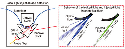
3. Local light injection and detection technologyThe technology we developed consists of matching convex and concave blocks for bending the optical fiber and probe fiber with a gradient index (GRIN) lens (Fig. 2). Optical signals are input and output by setting the probe fiber in the path of light leaking from the fiber bend. We call this local light injection and detection [2]. Conventional optical-fiber identification is limited with regard to performance since it uses a low-speed signal of 270 Hz as the leaked light. In contrast, our technology can handle high-speed signals, up to 1 GHz, as the leaked light and can input optical signals to the bent fiber via the probe fiber. These unique functions are achieved by optimizing the input/output efficiency of the light leakage from the bent fiber.
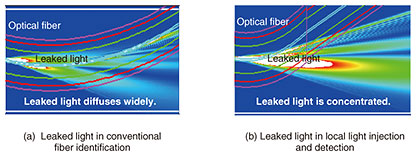
The contour map of leaked light intensity from a typical bent fiber is shown in Fig. 3. In conventional optical-fiber identification, the leaked light diffuses in the free-air gap (Fig. 3(a)). Our technology generates strong leaked light by imparting the local bend shape precisely designed with a bend radius on the millimeter order to the optical fiber (Fig. 3(b)). To receive leaked light with high efficiency, the probe fiber has a large core diameter and is equipped with a GRIN lens. Since the parameters of these optical devices are optimized for efficient reception of leaked light, our technology offers a 30-dB improvement in input/output efficiency compared with the conventional technology.
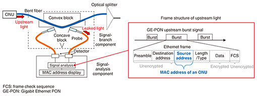
By drastically improving the efficiency of capturing/injecting leaked light, new applications can be developed. The following sections introduce specific applications. 3.1 Optical-fiber identification below an optical splitter by media access control address of the ONUThis section introduces one application of our local light injection and detection technology, which monitors upstream signals of the ONU from leaked light. The upstream signal transmitted from the ONU in a customer’s premises is received as leaked light (Fig. 4). The media access control (MAC) address of the ONU is stored as the source address in the ONU signal frame. The MAC address of the ONU connected to the target optical fiber can be captured by analyzing the leaked light [3]. Therefore, it is possible to confirm which ONU the target fiber is connected to, that is, to identify the optical fiber below an optical splitter.
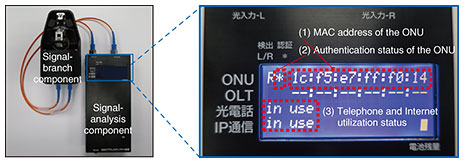
The prototype ONU MAC address capture device and examples of its measurement results are shown in Fig. 5. The prototype device displays (1) the MAC address, (2) authentication status, and (3) utilization status of the ONU. The upstream signal of the ONU also contains frame information about the authorization and utilization status of the ONU, in addition to the MAC address of the ONU, which allows (2) and (3) to be displayed. Currently, field engineers have difficulty in checking whether an ONU has been certified and the status of its service utilization because it is necessary to confirm certification light emitting diode of the ONU on/off at a customer’s premises or carry out a loopback test from the central office. With our technology, field engineers can check the status of the ONU in real time at worksites.
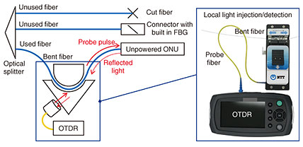
3.2 Fiber-termination identification by reflection analysis with optical time domain reflectometryA second application of our technology is a test technique to determine whether an unpowered ONU is connected to the target optical fiber. When installing optical fiber, field engineers must check whether the target optical fiber is used fiber or unused fiber. One method determines whether an optical fiber is used or unused by checking for the presence or absence of the ONU’s upstream signal from leaked light. However, this method cannot accurately be used to determine whether the optical fiber is used fiber or unused fiber because it cannot distinguish unused fiber from fiber connected to an unpowered ONU. One solution is to use optical time domain reflectometry (OTDR). However, there is no port at which the probe pulse from the OTDR can be launched into the optical fiber. To solve this problem, we developed a technique to determine whether an unpowered ONU is connected to an optical fiber without a test port by applying our local light injection and detection technology (Fig. 6). This technique enables test measurement by injecting OTDR probe pulses into the fiber under test through a fiber bend [4]. If the test measurement is to have sufficient accuracy, it is necessary to inject light into the bent fiber with high efficiency. Since the core diameter of an optical fiber is about 10 µm, highly accurate optical arrangements is required. Our technique offers high coupling efficiency, as we optimize the optical parameters such as beam waist and focal length of the GRIN lens, and the beam incident angle to the bent fiber. These characteristics have enabled high-efficiency light injection from the outside into the bent fiber.
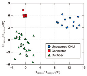
Measurement results of the map of reflectivity ratios at R1310 nm/R1550 nm and R1650 nm/R1310 nm are shown in Fig. 7. Here, the reflectivity at x nm wavelength is defined as Rx nm. We measured the fiber under test with three termination cases: unpowered ONU, optical connector with built-in fiber Bragg grating (FBG), and a cut fiber. The measurement results yielded a map of reflectivity ratios of fiber termination at multiple wavelengths. As shown in the figure, the three termination cases occupy different regions on the map. Therefore, these cases can be identified by simple threshold determination on the map.
4. Future perspectivesWe gave an overview of our local light injection and detection technology, which inputs and outputs optical signals by subjecting optical fibers to precise bending, and examined its applications. The upstream signal monitoring of the ONU and reflected light analysis of fiber termination, which were introduced as applications, make it possible to identify the optical fiber below an optical splitter and whether it is used fiber or unused fiber. Hence, field engineers can check the status of optical fibers in real time at the worksite. This technology will drastically improve the efficiency of construction work and be used commercially as a test tool for the construction and maintenance of optical fiber networks. References
|
|||||||||


