 |
|||||||||||||||||
|
|
|||||||||||||||||
|
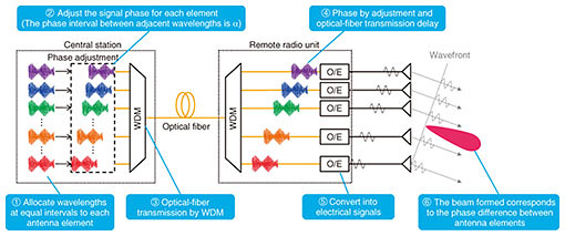
Feature Articles: Network-service Technologies Enabled by the All-Photonics Network for IOWN Vol. 19, No. 10, pp. 38–43, Oct. 2021. https://doi.org/10.53829/ntr202110fa4 Wireless Technology for Extreme NaaS—Remote Beamforming Schemes for Analog Radio-over-fiber-based High-frequency-band Wireless Communication SystemsAbstractAs one of the wireless communication technologies for extreme NaaS (network as a service), NTT Access Network Service Systems Laboratories previously proposed a system configuration to effectively expand the coverage area of high-frequency-band wireless systems. This configuration can separate the functions of a wireless base station and simplify remote radio units by using the analog radio-over-fiber technique. High-frequency-band wireless systems require beamforming to improve receiving sensitivity. This article describes remote beamforming schemes to enable beamforming with simplified remote radio units. Keywords: radio-over-fiber, beamforming, high-frequency-band wireless communication 1. IntroductionOne key component of extreme NaaS (network as a service) is wireless communication systems that use high-frequency bands such as millimeter-wave band. High-frequency-band wireless systems can enable larger transmission capacity through their wider bandwidths. However, many wireless base stations must be densely deployed because the propagation loss becomes large as the frequency increases. Therefore, we previously proposed a system configuration that uses the analog radio-over-fiber (RoF) technique to separate the functions of wireless base stations into a central station (signal processing unit) and remote radio unit (antenna unit) [1]. Signal-processing functions, including analog-to-digital (A/D) and digital-to-analog (D/A) conversions, are executed in the central station, and simple remote radio units are connected via analog RoF links. Since our configuration drastically simplifies the remote radio units, coverage-area expansion can be efficiently achieved. Our configuration is expected to be a promising area-expansion technology for sixth-generation mobile communication (6G) systems [2]. Beamforming to improve receiving sensitivity is necessary in high-frequency-band wireless systems since their propagation loss is significant. To enable beamforming with simplified remote radio units that have no signal processing unit, it is necessary to remotely control beamforming by the central station. Therefore, we also previously proposed two remote beamforming schemes that enable the central station to remotely control beamforming by remote radio units [3, 4]. Since these remote beamforming schemes have both advantages and disadvantages, it is important to apply the appropriate remote beamforming scheme for each use case. This article details these remote beamforming schemes and describes suitable use cases. 2. Problems with existing remote beamforming schemesExisting remote beamforming schemes control the beam direction by changing the wavelength assigned to each antenna element and using the chromatic dispersion of the optical fiber link [5, 6]. However, these schemes have the following limitations; (1) optical fiber length information is required, (2) optical filter control in remote radio units is required, and (3) wireless signal form is restricted if high-frequency bands or long optical fibers are used. Therefore, it is difficult to apply these schemes for function separation of high-frequency-band wireless systems. 3. Scheme (1): Remote beamforming scheme with fixed wavelength allocationScheme (1) is a remote beamforming scheme with fixed wavelength allocation. This scheme is explained using the example of a transmitter (Fig. 1). The central station assigns a fixed wavelength to each antenna element; wavelength division multiplexing (WDM) combines the signals and transmits one optical signal to the remote radio unit. Due to the chromatic dispersion of the optical fiber link, signals input to each antenna element have different time delays depending on the wavelength and optical fiber length. However, if the wavelengths corresponding to each antenna element are allocated at narrow and equal intervals, the time delays due to chromatic dispersion will also be equal. Therefore, the antenna elements receive input signals that have equal phase differences. When signals with equal phase differences are transmitted from each antenna element, signals to be transmitted are synthesized in-phase to yield a certain beam direction. The beam direction is determined by the phase difference between antenna elements. Therefore, beam direction control is possible by adjusting the phases corresponding to each antenna element beforehand to have equal phase differences, while arbitrary equal phase differences are achieved by adjusting the phases and adding phase rotation by optical fiber transmission.
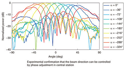
We investigated the applicable conditions and the effectiveness of scheme (1) through simulations and experiments [7]. We conducted a verification experiment using 10-GHz signal frequency, a 4-antenna element linear array in the remote radio unit, 10-km single mode fiber, and 1500-nm band wavelengths. The beam direction can be controlled by changing the phase interval (α) between adjacent wavelengths at the central station. Figure 2 shows the results of this experiment in which the beam direction was scanned by changing α at the central station; the wavelength interval was set to 50 GHz. The results confirmed that changing α changes the beam direction. We also confirmed that the obtained beam patterns in the experiment was almost equal the ideal beam pattern for a 4-antenna element array antenna. The wavelength interval of 50 GHz is one of the intervals specified in the dense WDM standard. This experiment confirmed that scheme (1) can enable almost ideal beamforming even when using off-the-shelf devices that comply with industrial standards and that continuous beam scanning is possible by phase adjustment in the central station.
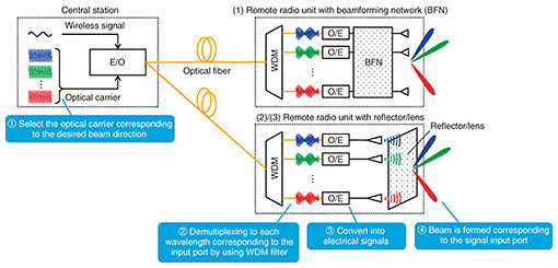
In scheme (1), there are restrictions on wavelength allocation because it is necessary to allocate wavelengths at narrow and equal intervals. Since the number of wavelengths must equal that of antenna elements used, the number of antenna elements is limited, and it is difficult to apply for massive antenna arrays. Since the remote radio unit requires only optical-to-electrical (O/E) conversion, each remote radio unit can be greatly simplified. Scheme (1) can form beams in arbitrary directions. Therefore, it is suitable for cases in which the area covered by one remote radio unit is relatively small, and a massive antenna array is not required, for example, room-based remote radio units in an office building that are connected to the same central station. 4. Scheme (2): Remote beamforming scheme using passive beamformerScheme (2) is a remote beamforming scheme that uses a passive beamformer (Fig. 3). The remote radio unit has the passive beamformer, and different wavelengths are assigned to its input ports. The central station selects and uses the wavelength assigned to the input port corresponding to the desired beam during electrical-to-optical (E/O) conversion. The signal transmitted from the central station is then passed to only the input port corresponding to the desired beam after passive WDM filtering and O/E conversion by the remote radio unit. Therefore, the input port of the passive beamformer can be switched by selecting the wavelength at the central station, and the beam can be switched remotely.
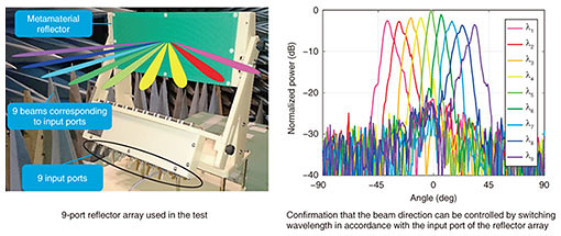
We tested scheme (2) using prototype devices [8]. This test was conducted with 28-GHz band wireless signals, 20-km single mode fiber, and 1500-nm band wavelength. A reflector array was also used as the passive beamformer in the remote radio unit. The reflector array consists of feeding antennas that radiate radio waves and a reflecting surface made of metamaterial. The metamaterial reflector is designed so that the reflecting directions of waves radiate from the feeding antennas depending on the positions of the feeding antennas. Since the radiated waves are reflected strongly in specific directions, beams can be formed. The beam direction can be changed by changing the feeding antennas. In the test, the reflector array had nine feeding antennas, thus formed nine beams, as shown in Fig. 4 left side. The beam direction can be switched by switching the feeding antenna to which the signal is input. The input ports of each feeding antenna are assigned wavelengths in the 1500-nm band with 100-GHz intervals, and beam patterns are measured while switching wavelengths used for E/O conversion at the central station. The results shown in Fig. 4 right side confirm that the beam direction changes with the wavelength, which is selected at the central station. The reason the beam gain decreases as the beam direction diverges from the front is due to the reflection characteristics of the reflector array.
It is necessary to set a beamformer at the remote radio unit so that the functionality of the remote radio unit will increase and installation sizes will be larger than with scheme (1). Since beam direction is determined by the design of the beamformer, there is a problem that only discrete beam directions are possible. However, when high beamforming gain is required, fewer wavelengths are needed compared with scheme (1) because the number of beams is expected to be lower than that of antenna elements when using massive antenna arrays. It is also possible to form multiple beams simply by inputting signals to multiple input ports. Since only one wavelength is used for one beam, there are no restrictions on wavelength allocation. Therefore, scheme (2) is suitable when one remote radio unit covers a wide area and high beamforming gain is needed, for example, wide service areas outdoors. 5. Future outlookWe will continue to improve remote beamforming characteristics to reduce the number of wavelengths required, increase beamforming gain, and enable arbitrary beam directions. We will also consider integration with distributed antenna systems and try to support 6G toward high-frequency-band wireless systems using analog RoF. References
|
|||||||||||||||||


