 |
|
|
|
|
|
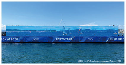
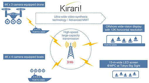
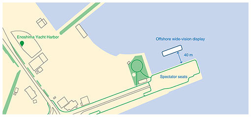
Feature Articles: Olympic and Paralympic Games Tokyo 2020 and NTT R&D—Technologies for Viewing Tokyo 2020 Games Vol. 19, No. 12, pp. 57–68, Dec. 2021. https://doi.org/10.53829/ntr202112fa8 Sailing × Ultra-realistic Communication Technology Kirari!AbstractNTT provided its ultra-realistic communication technology called Kirari! to the TOKYO 2020 5G PROJECT, which was implemented by the Tokyo Organising Committee of the Olympic and Paralympic Games to offer a new experience of sports viewing by using 5G (5th-generation mobile communication system). A new experience of watching sports at the sailing regatta, held at the Enoshima Yacht Harbor, is introduced in this article. In short, a sense of realism—as if the spectators were watching the races from close up—was provided by transmitting ultra-wide video images taken close to the race course to the spectators’ seats set up at the harbor. Keywords: 5G, Kirari!, live viewing 1. Overview of our initiatives at the sailing regattaIn sailing races, spectators usually have to use binoculars to watch the races (from breakwaters, etc.) because the races are held quite far from land. At the sailing regatta of the Olympic and Paralympic Games Tokyo 2020, we took up the challenge of solving this problem by using communication technology to create an innovative style of spectating that goes beyond the real world; namely, the spectators feel as if they were watching the races from a special seat on a cruise ship. Ultra-wide video images of the races (with a horizontal resolution of 12K) were transmitted live to a 55-m-wide “offshore wide-vision” display near the spectators’ seats (Fig. 1) by using the 5th-generation mobile communication system (5G) and our ultra-realistic communication technology Kirari!.
Initiatives at the sailing regatta for the TOKYO 2020 5G PROJECT are summarized below:
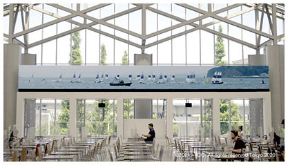
The ultra-wide video images were also transmitted live to Tokyo Big Sight, where the main press center (MPC) was located, to convey the realism of the event to media personnel whose movements were restricted within Japan because of the novel coronavirus (COVID-19) pandemic (Fig. 3).
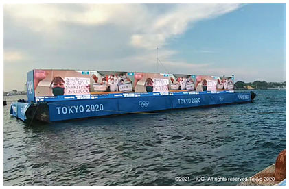
Although the sailing regatta was held without spectators, we implemented a measure called a “virtual stand” for sending support to the athletes from their far-away families and friends (Fig. 4).
2. Configuration of the video transmission systemThe configuration of the video transmission system for the sailing regatta is shown in Fig. 5. First, the sailing action is captured from boats or a drone equipped with multiple 4K cameras. The captured video images are synthesized as ultra-wide video images with 12K resolution and transmitted in real time by using Kirari! and 5G, which enables high-speed, large-capacity transmission. The transmitted images were displayed in real time on a 55-m-wide offshore wide-vision display floating in front of the viewing area at the regatta venue and on a 13-m-wide light-emitting diode (LED) display installed at the MPC at Tokyo Big Sight.
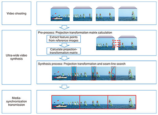
3. Technology3.1 Ultra-realistic communication technology Kirari!Kirari! is a communication technology that enables spectators to experience a race or other sports events as if they were in the stadium even when they are far away from it. In this project, we implemented two technological elements of Kirari!, video transmission using ultra-wide video-synthesis technology and ultra-realistic media-synchronization technology. 3.1.1 Ultra-wide video-synthesis technologyThe process flow of ultra-wide video synthesis is shown in Fig. 6. First, the optical axes of each of four cameras are aligned as much as possible, and the cameras are set up so that their shooting ranges overlap adjacent captured images by 20–40%. Before the actual synthesis process, as a pre-processing step to correct the disparity between each camera, a projection-transformation matrix is calculated from feature points extracted from a reference still image. For sailing, an image was taken of the competition yachts waiting just before the race as the reference image. To implement the pre-processing, we optimized the entire process from acquisition of the reference image to determining the wide-image-synthesis parameters by compressing the image data and reducing the transmission time by two-thirds, for example. Next, during the synthesis process, video frames were combined using a projection-transformation matrix calculated for each video frame to correct disparities and find appropriate seam lines in the video images (i.e., a process called “seam search”). The synthesis process is characterized by three features: synchronous distributed processing, accelerated seam search, and use of a graphics processing unit (GPU).
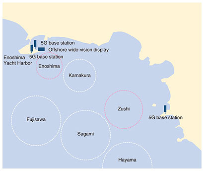
For synchronous distributed processing, the synthesis process is distributed to multiple servers (in accordance with the input and output conditions) so that a huge amount of video processing can be executed in real time. To synchronize the synthesis timings in each server, the same time code is given to the video frames when they are input, and this time code is propagated to the transmission devices (such as encoders) in the subsequent stages. As a result, synchronization of frames can be controlled across the entire system. The time code can be selected with either of two methods: (i) using the time code superimposed on the input video or (ii) generating the time code when the video is input. The seam search is sped up in two ways: (i) using the movement and shape of moving bodies obtained by analyzing the video frames during the seam search or (ii) using the seam position of the past video frame to prevent the seam position from fluttering. If the seam search for the next frame is executed after the seam search for the previous video frame is completed, it becomes difficult to achieve real-time synthesis. Accordingly, a two-stage seam search is conducted on a reduced video frame as a pre-search, and the pre-search result is used in the seam search of the next frame. For GPU-based acceleration of the seam search, almost all video processing is executed on the GPU, so processing is more intensive and faster. As a result of using the GPU, the video input from the serial digital interface (SDI) board is transferred to the GPU with minimal central-processing-unit cost, and the subsequent video processing is executed by the GPU. For example, when synthesizing 12K (4K × 3) ultra-wide video images from images captured with the four 4K cameras, it was possible to reduce the number of servers required by two-thirds (from six to two) compared with when the GPU was not used. 3.1.2 Ultra-realistic media-synchronization technology (Advanced MMT)The video images generated using the ultra-wide video-synthesis technology are divided into multiple 4K images for transmission so that they can be handled by general display devices, encoders, and decoders. In this case, the image on the display was 12K wide and 1K high, so it was divided into three 4K images. Kirari! uses advanced MPEG Media Transport (MMT) technology to perfectly synchronize the playback timing of individual images and sounds that are transmitted in separate segments. Ultra-realistic media-synchronization technology (Advanced MMT) synchronizes and transmits multiple video and audio with low delay by using UTC (Coordinated Universal Time)-based synchronization control signals that comply with the media transmission standard MMT. This technology can (i) synchronize and display not only wide-angle video images but also multi-camera-angle video images (2K, etc.) that track a specific athlete and (ii) absorb the difference in delays due to the network (dedicated line, Internet, wireless local area networks, etc.) that transmits each camera image or audio signal and device processing. This enables an ultra-realistic viewing experience in which multiple videos and audio are completely synchronized. 3.2 Wireless communication technologyThe races of the sailing regatta at the Olympic and Paralympic Games Tokyo 2020 were held on six race courses (Fig. 7). Two of those race courses, “Enoshima” and “Zushi,” were chosen for our initiatives. Ultra-wide video images were captured from three camera boats for the Enoshima course, and ultra-wide images were captured using a drone camera in addition to three camera boats for the Zushi course. 5G base stations were set up near both courses at the points shown in the figure.
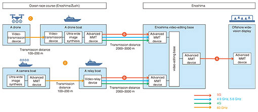
The configuration of the network used in this project is shown in Fig. 8. For uplinking video from the boats to shore and downlinking from the video-editing base to the barge-mounted offshore wide-vision LED display, NTT DOCOMO’s 5G line was used as the core in conjunction with multiple wireless communications with different characteristics such as bandwidth, distance, and directionality. NTT DOCOMO’s 4G line was used for flight control of the drone, backup video, and control of the server located on the camera boats.
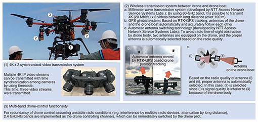
3.2.1 5G downlink transmissionThe video transmission between the video-editing base and barge-mounted offshore wide-vision LED display was carried out using NTT DOCOMO’s 5G access premium service. A commercially available customer premises equipment (CPE) terminal was used as the receiver. During the regatta, 200-Mbit/s video transmission was continuously operated for more than eight hours a day, achieving stable video transmission. 3.2.2 5G uplink transmissionNTT DOCOMO’s 5G access premium service was mainly used for transmission of drone video. A commercially available CPE terminal was used as the receiver. Six 2K video images were transmitted at an average bandwidth of 80 Mbit/s. NTT DOCOMO’s 4G service was used for backup of video transmission at a total rate of 50 Mbit/s. 3.2.3 Transmission of video images from a droneThe system configuration of a drone used to capture video images of the races is shown in Fig. 9. The drone was fitted with three 4K cameras. Three streams of 4K video taken by a drone were transmitted to a drone boat, from which the drone is launched and landed via 60-GHz wireless communication. The three video streams were time-synchronized for transmission. On board the drone boat, wide video images were synthesized and synchronously transmitted to the video-editing base at Enoshima via the 5G access premium service and Advanced MMT (Fig. 8).
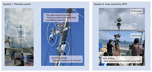
For the video transmission between the drone and drone boat, 60-GHz wireless-communication technology developed by NTT Access Network Service Systems Laboratories was used. For the wireless equipment, it is necessary to keep the antenna surface facing the drone all the time. To ensure more-stable wireless communication, we developed a technology that automatically controls the direction of the antenna by using real time kinematic (RTK) GPS (Global Positioning System) information so that the antenna always points in the direction of the drone. Depending on the shooting angle of the drone, the drone may create a blind spot for wireless communication. To solve this problem, we developed a technology for automatically switching the antenna in accordance with the wireless-signal strength. The above technologies enable stable video transmission between the drone and drone boat in a manner that gives the drone more freedom to shoot video. As a security measure for the drone, the flight control of the drone was duplexed using two 4G wireless signals, one at 4 GHz and the other at 2 GHz. 3.2.4 Transmission of video images from camera boatsThe following requirements for transmission of video images from the camera boats were set: 1. Since the race course may be changed at short notice due to weather conditions or wind direction, the camera boats should be able to move flexibly. 2. Depending on the race course used, wireless transmission over a distance of 2 to 3 km is required. To meet these requirements, we prepared a “relay boat”—separate from the camera boats—for long-distance wireless transmission to the land. For transmission of video between the camera boats and relay boat, 60-GHz wireless communication, which has a short transmission distance but a large data-transmission capacity, was used. To allow the relay boat to move flexibly, the boat was fitted with a wireless antenna with a relatively wide angle of directivity. In addition to 5G, 4.9-GHz and 5.6-GHz wireless communications were used to transmit video images from the relay boat to land (Fig. 8). While these wireless communications can transmit over long distances, the antenna directionality is strong, so the antenna surfaces of the transmitter and receiver must always be aligned. Two mechanisms for controlling the antenna were developed (Table 1 and Fig. 10).
The type of boats was selected by applying a bit of ingenuity. Since it was necessary to film the races close up, small fishing boats were selected as the camera boats because they would not affect the navigation of the racing yachts. A large fishing boat that can suppress rocking even in open seas was selected because it has to transmit wireless signals over 2 to 3 km. For the on-land antennas, it was not always possible to secure a roof top of a tall building along the coastline. Accordingly, a vehicle was fitted with a pole that could be raised high above the vehicle, and the antenna was attached to the top of the pole to ensure a clear line-of-sight to the relay boat. The 60-GHz band enables transmission at 100 to 200 Mbit/s over a distance of 100 m (i.e., boat-to-boat distance), while the 4.9- and 5.6-GHz bands enable transmission at 50 to 150 Mbit/s over a distance of 2 to 3 km (boat-to-land distance). Communication speed depended on the condition of the ocean waves. During the approach of typhoon Nepartak, the waves were high, so it was difficult to control the antennas of the wireless transmitters, which significantly reduced communication speed. 3.3 Offshore wide-vision displayTo create a sense of realism as if you were watching the races up close, highly realistic video images and a space to make use of those images are required. To meet the first requirement, actual-size images of the competition yachts, a display size that covers the entire field of view, high resolution, and a display with no noticeable dots are needed. The offshore wide-vision display was 5 m high and 55 m wide with a horizontal resolution of 12K and vertical resolution of 1K. Although the pitch size was 4.8 mm, as shown in Fig. 11, it was installed 40 m from the spectators’ seats, so the roughness of the image was not noticeable because it exceeded the spectators’ retinal resolution.
To meet the second requirement, the space in which the display is set up is also important. Since the display is like a rectangular cut-out, it inevitably leaves an unnatural feeling in the same manner as a television. By floating the display on the ocean and merging its boundaries with the natural sky and sea, it was possible to create a natural sense of realism. When the offshore wide-vision display was installed, we set up an organization containing not only specialized members who design and build LEDs but also those who carry out structural calculations on the basis of the undulation of the sea surface, those who navigate and moor boats, marine-procedure agents, weather forecasters, etc. and studied the following points in consideration of the weather at the actual regatta. We collected meteorological data for Enoshima in July and August over the past 10 years to understand wind speed, wind direction, wave height, etc., evaluated the strength of the designed LED display and the safety of the means of mooring the barge of the floating display, and determined the criteria for evacuating the site of the offshore wide-vision display. To meet the evacuation criteria, the display was operated under the condition that wind speed did not exceed 25 m and wave height (swell) did not exceed 1.6 m. The criteria were determined after careful considerations of the members specializing in marine weather based on not only the intensity of the LEDs and the strength of the mooring of the floating-display barge but also the weather conditions on Enoshima Island and on the waters off Miura Peninsula in case of evacuation to Odaiba in Tokyo. During typhoon Nepartak, which occurred during the regatta, weather information was constantly monitored, and possible evacuation was determined on the basis of the above-mentioned criteria. As a result of that monitoring, it was determined that no evacuation was necessary, and the display was operated without incident. 3.4 Wave-undulation correction technologyWhen filming from a boat on the ocean, the captured video images will flicker due to the rocking of the boat. We therefore developed a technology for compensating for this video flickering in real time. The developed technology uses optical flow to detect the direction of the video flickering and correct it in real time to minimize as much flickering as possible. 4. ResultsDuring the regatta, the video transmission went smoothly without any major problems. Although the regatta was not attended by spectators, hundreds of people, mainly athletes and related support people, watched the video transmission every day of the regatta. We received comments from many people of those that expressed their surprise, excitement, and hopes for the future of sailing. Some comments were “I was surprised by the high sense of realism that I have never experienced before,” “I really wish the general public could see this,” “It made it easy to understand the race situation,” and “If this style of spectating becomes common, the number of sailing fans will increase rapidly.” For our aim of creating “a sense of realism, as if the race was being held in front of you,” we were able to create the experience of “warping into the race space itself” by fusing the powerful, actual-size race images displayed on the offshore wide-vision display floating on the sea with the actual surface of the sea, sky, and other real spaces. Technically, issues still had to be solved. These issues include (i) unstable wireless communication, including 5G, in certain situations and (ii) slight disturbance in the video images because the camera boats and drone could not completely absorb the undulations due to the waves and engine, respectively. However, we believe that we were successful in an environment that demands a very high level of performance. 5. Concluding remarksUsing commercial 5G and our in-house ultra-realistic communication technology Kirari!, we successfully transmitted live ultra-wide video images (with 12K horizontal resolution) via a 55-m-wide offshore wide-vision display installed at the Enoshima Yacht Harbor site and a similar but smaller display at the MPC at Tokyo Big Sight in Tokyo. At both sites, the live video transmissions were highly evaluated by athletes, officials, and international media. The communication technology used in this project will enable live viewing not only within a competition venue but also to remote locations, including overseas ones. Even during the COVID-19 pandemic, this project can be ranked as a showcase for achieving a remote world that NTT is aiming for. From now onwards, we will promote further research and development on communication technologies, mainly in the fields of sports and entertainment, using 5G and the All-Photonics Network of IOWN (Innovative Optical and Wireless Network) as an infrastructure. AcknowledgmentsWe thank all members of the TOKYO 2020 5G PROJECT, the Innovation Promotion Office of the Tokyo Organising Committee of the Olympic and Paralympic Games, and Intel Corporation who worked with us on the project. We also thank the Functional areas (FAs) of the Tokyo Organising Committee of the Olympic and Paralympic Games, World Sailing, and Japan Sailing Federation for their cooperation in implementing this project, and the Enoshima-Katase, Koshigoe, and Kotsubo Fishing Cooperatives for providing the necessary boats we used for filming. Finally, we particularly want to thank Tatsuya Matsui, the chief engineer in charge of EEP infrastructure, and Hikaru Takenaka, who was in charge of network construction for this sailing project. NTT is an Olympic and Paralympic Games Tokyo 2020 Gold Partner (Telecommunication Services). |
|


