 |
|||||||||||||||||||||||
|
|
|||||||||||||||||||||||
|
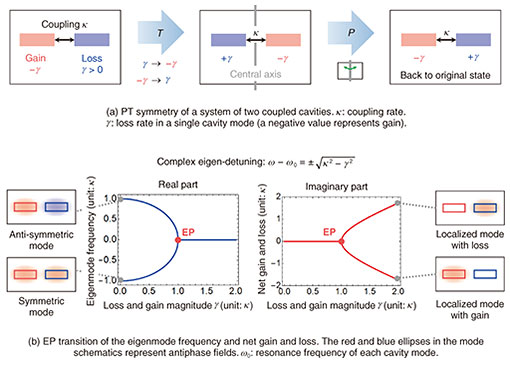
Feature Articles: Device Technologies for Enabling the All-Photonics Network Vol. 20, No. 8, pp. 35–41, Aug. 2022. https://doi.org/10.53829/ntr202208fa4 Observation of Exceptional Point Degeneracy with Current-injected Photonic Crystal LasersAbstractCoupled resonators and coupled waveguides with contrast of their gain and loss are non-Hermitian optical systems, which are based on energy-non-conserving processes. They have been reported to exhibit a number of unconventional phenomena that are expected to contribute to practical applications. We developed a coupled system of two current-injected photonic crystal lasers that enable precise control of gain and loss, thus establishing a promising non-Hermitian nanophotonic platform. We introduce our demonstration of a peculiar non-Hermitian mode degeneracy called an exceptional point (EP) and the EP-based enhancement of spontaneous emission with this system. Keywords: non-Hermitian photonics, exceptional point, photonic crystal lasers 1. Non-Hermitian photonicsTo generate and control optical signals, devices such as lasers, modulators, and photodetectors are required. They vary the intensity of light by amplifying it via stimulated emission, releasing it from optical signal channels, or absorbing it with the generation of electric carriers. In the Maxwell equation of electromagnetism, optical amplification gain and absorption loss in a medium are expressed as the imaginary part of its refractive index. When resonators and waveguides comprise media with finite imaginary parts of refractive indices, possible states of electromagnetic waves confined in them (eigenmodes) have generally complex frequencies and propagation constants (eigenvalues). The imaginary part of the eigenvalue corresponds to the rate of optical gain or loss per unit time for a resonator and per unit propagation distance for a waveguide. A system is called Hermitian when the energy of the physical quantity of interest (light waves here) is conserved. In contrast, a system based on energy-non-conserving processes is non-Hermitian. Since the mode eigenvalues of a non-Hermitian optical system are complex numbers, as mentioned above, light waves there may continue to be amplified or absorbed until the carrier response is saturated or may be totally radiated out. Unlike Hermitian systems, eigenmodes of non-Hermitian systems are generally not orthogonal to each other. Given that it is impossible to measure a completely closed system without energy dissipation, all the states we observe are those of non-Hermitian systems. This means that every state of optical systems may not be independent but more or less mixed with other ones. Responses of such non-Hermitian systems seem to be much more diverse and difficult to understand compared with Hermitian systems that are assumed as approximations in many cases. In addition, gain and loss had been considered to only control the intensity of light in photonics. Thus, the research for other applications of them had been limited. 1.1 PT symmetryA turning point in these circumstances was the introduction of the concept of parity-time (PT) symmetry to photonics [1] by the group headed by Professor Christodoulides at the University of Central Florida. Parity in PT symmetry means spatial inversion. This corresponds to setting a central axis or plane of symmetry (double-sided mirror) in space then inverting the system (or jumping to the world on the other side of the mirror). Time in PT symmetry stands for time reversal, which means turning gain to loss and loss to gain. A system is said to have PT symmetry when both of these operations make it get back to its original shape. While PT symmetry has attracted attention in quantum mechanics, Makris et al. showed that the analogy of PT symmetry in the above-mentioned sense held in the refractive index distributions of optical systems. They also showed that such a system could have a peculiar mode degeneracy called an exceptional point (EP). We now explain the characteristics of a coupled two-cavity system with PT symmetry shown in Fig. 1(a). We assume that each resonator has an eigenmode (cavity mode) with an identical resonance frequency when isolated. The cavities are placed in proximity with an interval of the order of the mode wavelength. Thus, a small number of fields of one cavity mode seeps into the other via the evanescent wave*1 so that they are coupled with each other. The system is PT-symmetric when two cavities have loss and gain with the same magnitude γ. Note that the gain rate is denoted as a negative value of –γ, which is contrasted to that of the loss γ > 0. 1.2 EP phase transitionFigure 1(b) shows how the system response changes when the coupling rate is fixed to κ and the γ of the balanced gain and loss is varied. The left and right plots respectively show the eigenmode frequencies (the real part of the complex eigenfrequency) with reference to the single cavity mode frequency ω0 and their net loss rates (the imaginary part of the complex eigenfrequency) for which negative values mean gain. When γ = 0, which corresponds to the Hermitian system, the two eigenmode frequencies are split by 2κ by the coupling. The eigenmode distributions are two orthogonal states termed symmetric and antisymmetric. As γ increases, the frequency splitting decreases then changes abruptly toward zero near γ = κ. In this case, because both eigenmodes distribute an equal field intensity for the two cavities with balanced gain and loss, their net loss or gain rates are exactly zero. When γ > κ, the two mode frequencies are the same. In contrast, the eigenmodes’ loss or gain rates split sharply into positive and negative values. Despite the fact that the cavities are supposed to be coupled, the eigenmodes become localized by the increase in γ; one concentrates in the cavity with gain, hence amplified, and the other is in the lossy cavity, thus damped. When the gain, loss, and coupling rates are equal (γ = κ), the eigenmode frequencies coincide, and the net loss or gain rates remain zero just before the bifurcation. What happens is not the accidental degeneracy of two different states with the same complex frequency; the distributions of the two modes rather become completely the same. Thus, there is only a single state. The degeneracy in this sense is a phenomenon peculiar to non-Hermitian systems and termed an EP. It can also be said that an EP is a phase-transition point from modes spreading over the entire system to those localized in cavities with gain or loss.
To date, a number of unconventional phenomena based on this EP phase transition have been reported, and readers can refer to a previous review article [2]. Examples include non-reciprocal propagation*2, single-mode oscillation, and the enhancement of frequency perturbation effect, each of which has a good potential for practical use. Non-reciprocal propagation is a necessary condition for an optical isolator that protects a laser against instability by undesired optical feedback. Although integrating an optical isolator into a photonic circuit is technically difficult, it is an important element to complete optical information processing within a chip. Unfortunately, the non-reciprocal property near an EP is valid only for a certain range of the input light intensity because it is based on gain saturation. Thus, further studies are needed to pave the way for achieving a practical isolator based on an EP.
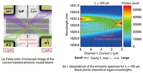
2. Observation of EP degeneracy by coupled photonic crystal laserThere are very few examples of observing EP degeneracy in photonics because of certain technical problems. One issue is the need for precise control of gain and loss. An EP is actually a point in the gain and loss parameter space, around which the complex eigenfrequencies vary greatly. Therefore, to observe EP degeneracy, it is necessary to control the gain and loss of each cavity independently and continuously. Another issue is the change in individual cavity frequency in controlling gain and loss. Regarding coupled cavities with the above-mentioned controllability, integrated systems of multiple semiconductor lasers are considered first. However, since driving them is accompanied by the generation of heat and free carriers, the real part of the refractive index of each cavity medium also changes when the gain and/or loss difference is introduced. As a result, the resonant frequencies of the two cavity modes diverge. Because this frequency detuning is known to lift EP degeneracy, it is necessary to use lasers with high excitation efficiency as much as possible to minimalize the impact of such an effect. 2.1 Current-injected photonic crystal laserWe fabricated the coupled system of two current-injected photonic crystal lasers [3] shown in Fig. 2(a). The system is structured on an indium phosphide (InP) thin film suspended in air. It has a two-dimensional photonic crystal with an array of air holes with a diameter of about 200 nm. Two wavelength-scale gain media*3 with quantum wells (red rectangles in the figure) are embedded in line defects without air holes and work as nanocavities. In addition, p-doped layers (purple parts) and n-doped layers (green parts) are formed in the oblique directions from the four electrodes (yellow parts), constituting two in-plane current-injection channels. Because this structure suppresses the leakage current between the electric channels, the gain and loss of each nanocavity can be controlled independently by current injection. To date, by using such a photonic crystal laser on the basis of a buried heterostructure nanocavity, we demonstrated the smallest laser threshold current in the world [4]. The low current drive of our system minimalizes the detrimental effect of the cavity-frequency detuning due to heat and carriers. In Fig. 2(a), the right and left cavities and current channels are numbered 1 and 2, and the inter-electrode current values for channel 1 and 2 are denoted as I1 and I2, respectively. The emission spectrum of the system was measured while I1 and I2 were varied. As a result, when I2 was fixed at 100 μA and I1 was decreased, a clear EP phase transition was observed. Figure 2(b) shows the color plot of such emission spectra for different I1. Here, I2 = 100 μA is the condition to compensate for the loss γ2 due to absorption and radiation in cavity 2 (γ2 ~ 0). However, a finite loss γ1 of resonator 1 remains. Consequently, the entire system does not oscillate, and weak spontaneous emission of photons is hence observed. As I1 diminishes, the two spectral peaks indicating coupled modes approach each other and eventually coalesce. This is because the difference in the loss of the two cavities is enhanced by the increase in γ1, resulting in the variation of the eigenmode frequencies similar to that in Fig. 1(b). By fitting the spectra using a theoretical model, we can estimate the resonance frequency of each cavity mode, cavity coupling κ, and loss γ1. We found that the system was very near the exact EP when I1 = 1.4 μA. The detrimental frequency detuning of the two cavities is also very small. This can be seen from the fact that the theoretical eigen-wavelengths (black points in Fig. 2(b)) calculated from the fitting result are aligned with a point in the relevant region. If I1 is further decreased, the peak photon number increases in spite of the magnified loss. This is thought to be because one of the eigenmodes is localized in resonator 2, which has a large injection current, becoming less susceptible to the loss of resonator 1. This intensity recovery also supports the EP phase transition illustrated in Fig. 1(b).
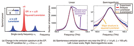
2.2 Spontaneous emission spectrum at the EPWe also clarified that the spectrum near the observed EP mentioned above indicated the peculiar enhancement of spontaneous emission. Even though the loss of one cavity is compensated and the other has a loss, the system with a large coupling exhibits a spontaneous emission spectrum that is expressed as the sum of two split Lorentzian functions*4 (blue spectrum in Fig. 3(a)). In contrast, the emission spectrum of the EP state takes the shape of the squared Lorentzian function (red spectrum in Fig. 3(a)) [5]. When the system can be approximated as a Hermitian one, the two modes are almost independent. Thus, even if their peaks coincide accidentally, the emission spectrum will only be the sum of them, that is, a Lorentzian function with twice their peak intensity. In stark contrast, the two modes degenerate into exactly the same state at the EP, exhibiting constructive interference in the spectral domain. Suppose we vary only the coupling κ that always preserves the energy so that the system is dragged to the EP condition while keeping the other parameters constant. In this case, we can measure the impact of the spectral change induced purely by EP degeneracy. Because of the maximum intensity change due to the interference, the peak intensity of the EP spectrum (colored red) is four times (= (1 + 1)2) larger than those of the split Lorentzian peaks (blue). From the energy conservation, the total integrated powers for the two spectra in Fig. 3(a) are equal, and the loss of the eigenmodes for them is also the same. Despite this, the peak intensity of the EP is enhanced via the spectral change in which the shape becomes squared-Lorentzian; thus, the linewidth becomes narrower than the Lorentzian peaks for the large coupling. Our system can control the gain and loss of each laser but not the coupling between the lasers. In our experiment, unfortunately, the effect of reducing the peak intensity by increasing γ1 was superimposed on the measurement results. Thus, the directly observed ratio of the peak-intensity enhancement by the EP is about 30%. However, as shown in Fig. 3(b), we also observed that the emission spectrum at I1 = 1.4 μA, which was closest to the EP, was a squared Lorentzian function. This result indicates that the system is under an almost exact EP degeneracy. This means that the effect of EP degeneracy can be clearly observed if the system approaches the states at which its complex-eigenfrequency splitting is small enough compared with the linewidths of the modes.
3. Future outlookIn this article, we introduced the observation of EP degeneracy with our current-injected photonic crystal lasers. We are now conducting experimental demonstrations of our other theoretical proposals, such as the control of group velocity using an EP [6] and that of photonic topology by gain and loss [7], by using more large-scale photonic crystal laser arrays. We are also exploring new principles and phenomena in non-Hermitian nanophotonics. References
|
|||||||||||||||||||||||


