 |
|||||||||||||||
|
|
|||||||||||||||
|
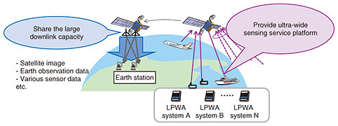
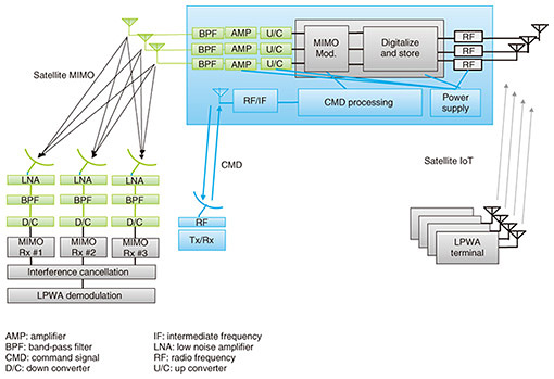
Feature Articles: Space Integrated Computing Network Vol. 20, No. 12, pp. 36–40, Dec. 2022. https://doi.org/10.53829/ntr202212fa4 Satellite Sensing PlatformAbstractThis article introduces a 920-MHz Internet of Things (IoT) platform via a low Earth orbit (LEO) satellite using feeder-link multiple-input multiple-output (MIMO) technology. In this platform, the LEO satellite captures the IoT radio waves transmitted from terrestrial low-power wide-area terminals onboard then downlinks them to the base station when it passes over the station. Since the received signals are directly digitalized as wave data, the amount of data stored is huge. To downlink this huge amount of data within the limited period in which the moving LEO satellite passes over the base station, we propose applying MIMO technology to the downlink from the LEO satellite to the base station. Keywords: satellite MIMO, satellite IoT, satellite blind beamforming 1. IntroductionVarious Internet of Things (IoT) services are rapidly spreading worldwide [1]. Satellite communications is widely used in places a terrestrial network cannot cover, so it is an effective approach to provide IoT services to such areas. Several satellite IoT services accommodate IoT traffic using devices and frequencies provided by the satellite operators [2, 3]. However, the initial and running costs are so high that the number of users is currently small. To address the cost issues, we propose using terrestrial 920-MHz low-power wide-area (LPWA) terminals for satellite IoT systems. We aim to lower the cost of IoT services via satellite by using terrestrial LPWA terminals and shared unlicensed frequency bands. 2. Satellite sensing platform2.1 ConceptFigure 1 shows the system configuration of our IoT platform [4]. The power-regulated terrestrial LPWA terminals can be used freely without a license in the 920-MHz frequency band. The radio waves emitted from the LPWA terminals are captured by a low Earth orbit (LEO) satellite. The captured waves are then digitalized and stored in the onboard memory. Finally, the stored data are downlinked to the base station. Demodulation is not carried out onboard, so our satellite IoT platform does not specify the communication protocol; it can correspond to any type of protocol. The stored data need to be downlinked in the limited time when the LEO satellite passes over the base station. Therefore, we propose applying multiple-input multiple-output (MIMO) technology to the feeder-link between the LEO satellite and base station. As Fig. 1 shows, the satellite MIMO technology executes spatial multiplexing transmission from a single satellite with multiple antennas to the base station connected with multiple remote antennas. The technical points and operational principles are introduced later.
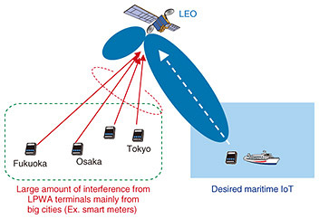
2.2 Key technologies(1) Satellite blind beamforming Since many terrestrial LPWA terminals share the unlicensed 920-MHz band, onboard receiver (Rx) antennas receive both the desired satellite IoT signals and undesired interference emitted from a huge number of terrestrial LPWA terminals. Therefore, they need to extract the desired satellite IoT signals and suppress interference. To achieve this, several Rx antennas are implemented onboard and downlink the received signals they capture to the base station. The desired signal is then extracted offline while interference-cancellation software suppresses undesired signals [5]. Figure 2 shows the concept of maximizing the power of a desired signal while suppressing the power of undesired signals. Multiple onboard antennas help channel the null directivity in the direction from which a large amount of undesired interference is emitted, simultaneously forming the peak directivity toward the desired LPWA terminal. This signal processing is carried out offline by using downlinked onboard wave data in the base station. This technique is called “satellite blind beamforming.” Since demodulation is also carried out using software, our platform can flexibly accommodate any type of LPWA protocol by installing the appropriate demodulator.
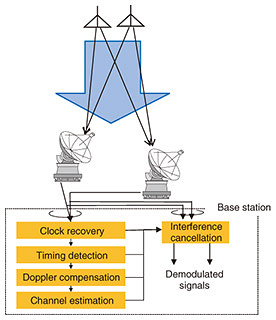
Our platform is based on the condition that signals of terrestrial 920-MHz LPWA terminals can be captured by the LEO satellite. Therefore, it needs to confirm that those received signals satisfy the required signal-to-noise ratio (SNR) for demodulation. Therefore, we investigate the coverage area of a satellite IoT terminal by calculating its link budget. A dipole antenna is assumed for the LPWA terminal antenna. The transmitter (Tx) power is 20 mW, the same regulation as a typical terrestrial LPWA terminal. LoRa (long range radio) (spreading factor: 12, bandwidth: 125 kHz) is used as a protocol so that its required SNR is 6 dB. The antenna gain depends on how the dipole antenna is set. We set the boresight directivity of the dipole antenna to be vertical to the Earth. We do not consider the undesired/unknown interference from other LPWA terminals for the fundamental link-budget calculation. There are three onboard Rx antennas, each of which is a circular, patch-type antenna with a peak gain of 6.5 dBi, and the –3-dB-bandwidth is 80 degrees. Since we do not consider the undesired signals in this calculation, we apply maximal ratio combining to the three received signals. Under the above condition, the maximal radius of the service coverage area (SNR > 6 dB) is about 640 km. (2) Satellite MIMO Figure 3 shows the operational principle of satellite MIMO [6]. By using a control channel for multiple Tx antennas, the Doppler frequency is removed and symbol timing is detected in the Rx. The channel matrix is then estimated, which is used to cancel the MIMO interference. The channel matrix and received SNR of LEO satellites are expected to change at each ground-antenna elevation angle and visible path. Because an LEO satellite moves around the Earth, it takes different positions when connecting to a ground station. The changes between the propagation distance, received SNR, and relationship between the Tx/Rx antenna positions are complicated for each visibility time and path. Therefore, the elements of the LEO-MIMO channel matrix must be analyzed at each visibility time to evaluate the capacity of the channel [7].
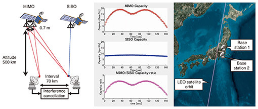
Figure 4 illustrates an example of the capacity enhancement using LEO-MIMO. Two antennas are mounted on the satellite with an interval of 70 cm and the interval between the two base stations is 70 km. For comparison, a conventional single-antenna satellite system, i.e., single input single output (SISO), is also being evaluated. The right side of Fig. 4 shows the capacity comparison while the LEO satellite is moving over Japan. The X axis shows time and Y axis shows capacity. The MIMO capacity is about double that of the SISO capacity. This means the MIMO technology can improve communications capacity corresponding to the number of antennas.
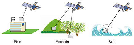
3. Satellite experimentsExperiments to confirm the practicality of a 920-MHz IoT platform via an LEO satellite using satellite MIMO technology are being considered. Figure 5 shows an experimental configuration with a scale model. Three antennas are implemented on the satellite as onboard 920-MHz IoT Rxes. We will also conduct 3 × 3 MIMO experiments. On the basis of our experience, we plan to use the X band for MIMO experiments. For IoT experiments, our plan is to evaluate satellite IoT performance under various conditions, as shown in Fig. 6.
4. SummaryWe proposed a 920-MHz IoT platform via a LEO satellite using feeder-link MIMO technology. We presented fundamental feasibility studies of the link budget calculation and estimation of MIMO channel capacity. References
|
|||||||||||||||


