 |
|||||||||||||||||||||||
|
|
|||||||||||||||||||||||
|
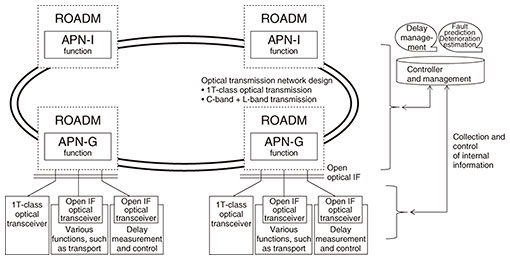
Feature Articles: Transport Network Technology for IOWN Implementation Vol. 21, No. 1, pp. 12–17, Jan. 2023. https://doi.org/10.53829/ntr202301fa1 Optical Transmission Technology for Practical Implementation of the All-Photonics NetworkAbstractNTT Network Innovation Center is developing technologies and systems for the practical implementation of an optical transmission network, the key element for implementing the All-Photonics Network (APN), which in turn will support IOWN (the Innovative Optical and Wireless Network). With our next-generation optical transmission network, which is an advance release of the APN, we are working to increase speed and capacity to handle growing communication traffic as well as provide open optical interfaces for connecting various systems and devices without photoelectric conversion to enhance the added value provided by optical networks and develop operations and maintenance technologies for these networks. Keywords: optical transmission, open optical interface, latency management 1. IntroductionBy introducing photonics-based technologies to the All-Photonics Network (APN) [1], which forms the foundation of the Innovative Optical and Wireless Network (IOWN), we are aiming to significantly enhance the potential of the information processing infrastructure. We also aim to achieve low-power-consumption, high-quality, high-capacity, and low-latency transmission by disaggregating and reconfiguring various functional parts of the APN using open interfaces. Our three performance targets are to increase transmission capacity by a factor of 125, electric power efficiency by a factor of 100, and reduce end-to-end latency by a factor of 200. Building the practical APN requires advanced engineering, which involves integration of state-of-the-art elemental devices and the latest technologies—under various conditions and constraints—such as open interfaces. As part of our effort toward the early social implementation of the APN, we are developing and engineering a next-generation optical transmission network, which will serve as an advance release of the APN. In developing this network, we are focusing on (1) studying a system configuration in which the most advanced optical communication devices and latest technologies and expertise are used to increase transmission capacity by a factor of 10, and in which the reconfigurable optical add/drop multiplexer (ROADM) function is separated from the optical transceiver function using an open optical interface to reduce photoelectric conversions, thus significantly reducing system power consumption; (2) developing a photonic transceiver that suppresses end-to-end latency and delay jitter in the Internet and a Layer 2 virtual private network by managing the absolute delay for applications that are sensitive to transmission delay and delay variation, an ability that constitutes one of the added values to be provided by the APN; and (3) studying maintenance and control subsystems for overall operation of these systems. 2. Achieving high-speed, wide-bandwidth, and open optical interfacesWhile the next-generation optical transmission network (Fig. 1) is based on dense wavelength division multiplexing and digital coherent technology, its transmission capacity will be increased by multiplexing optical signals of approximately 1 Tbit/s per wavelength across multiple wavelength bands. By disaggregating the ROADM function and optical transceiver function and specifying an open optical interface between them, we aim to enable connections to be established to remote locations using various optical transceivers without photoelectric conversions.
2.1 1-Tbit/s-per-wavelength-class optical signal transmissionTo boost the transmission capacity per wavelength (800 Gbit/s/wavelength for long-distance transmission and 1 Tbit/s/wavelength for short-distance transmission), the optical transceivers in the next-generation optical transmission network will use world-leading digital signal processors (DSPs)*1, which increase both the optical signal modulation rate and number of modulation levels. The optical design of the ROADM function component will also be revised to appropriately control optical noise and optical signal distortion to allow stable transmission of high-speed optical signals. 2.2 Multiplexing using multiple wavelength bandsTraditionally, NTT’s optical transmission networks have used dispersion shifted fiber (DSF) [2], which is considered suitable for long-distance transmission. However, DSF inherently involves zero-dispersion wavelengths, which cause large waveform distortions in high-speed optical transmission. Consequently, the C-band cannot be used for optical transmission, leaving only the L-band usable. Now that cut-off shifted fiber (CSF) [3] is available, the next-generation optical transmission network will adopt an optical and system design suitable for CSF. This will make both the C-band and L-band usable, doubling transmission capacity. 2.3 Open optical interfaceThe Open ROADM Multi-Source Agreement (MSA)*2 defines interfaces for multi-vendor connectivity and interoperability between functional parts of optical transmission networks. It is being extended to cover 400G-capable nodes [4]. Technical Specification 2.0 was also released [5] for Open ZR+ MSA, which defines interoperability specifications between pluggable optical modules such as quad small form-factor pluggable-double density (QSFP-DD)*3. Therefore, telecommunication carriers, hyperscalers, and optical module vendors are working together to accelerate the shift toward open and disaggregated optical transmission systems. These MSA standards will be adopted in the next-generation optical transmission network to achieve open optical interfaces and provide optical end-to-end connectivity for various systems and services targeted with the APN.
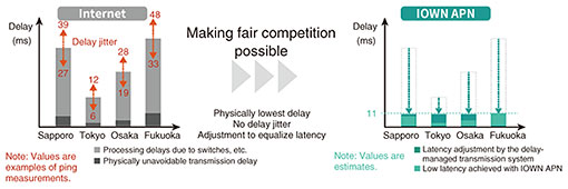
3. Optical transmission system capable of latency managementWe are developing a delay-managed transmission system. With increased sophistication in communication network usage and the COVID-19 pandemic, there has been a rapid increase in remote work and other remote activities. For activities that require coordination and synchronization among multiple locations, communication delays and delay jitters have significant impact on the user experience (UX). For example, in an e-sports tournament with players located at different sites, a fair match may not be possible if there are noticeable communication delays or delay jitters. If an e-sports server is located in Tokyo, there will be a time difference of approximately 30 milliseconds between Tokyo and Fukuoka (Fig. 2, left) due to transmission delays caused by the difference in physical distance (dark gray) as well as processing delays caused by routers and other devices in networks run by Internet service providers (ISPs) (light gray). Furthermore, the processing delay within ISP networks is not constant but varies with time (the length of the orange arrow) because it is affected by other non-e-sports traffic. Users with lower latency connections are generally able to react faster, giving a clear advantage to players in locations closer to Tokyo, where the server is located.
Our delay-managed transmission system will minimize delay by providing a communication environment that does not involve the Internet (Fig. 2, right, light green) and maintain fairness among users by assigning delays to lines in such a way that the delay of every line will be equal to that of the line with the largest delay (Fig. 2, right, dark green). This eliminates delay differences between users. This stable communication environment, characterized by ultra-low latency, no latency differences, and no delay jitters, makes fair competition possible. 3.1 Communication control using the OTN protocolThe delay-managed transmission system will use the Optical Transport Network (OTN)*4 protocol at Layer 1, which is the physical layer of the Open Systems Interconnection (OSI) reference model*5, to achieve low latency that is close to the physical minimum limit. Layer 1 communication is circuit-switched communication. Once a connection is established with the other end, the communication constantly occupies the bandwidth. Therefore, in principle, the bandwidth is fixed and no delay jitter occurs. In addition, when communication control is executed only at Layer 1, packet retransmission and packet queuing processes, such as those used in Layers 2 and 3, are not required, achieving low latency close to the physical minimum limit. To implement latency management, a device in the delay-managed transmission system measures end-to-end delay time using the delay measurement information specified in ITU-T G.709 and stores the OTN signal data in the first-in-first-out memory within the device, adjusting the delay time to that desired between the users concerned. 3.2 Demonstration for application to e-sports competitionsWe demonstrated an e-sports tournament involving fighting games at NTT R&D Forum - Road to IOWN 2021 held in November 2021 and docomo Open House ’22 held in January 2022. Two e-sports players belonging to a professional team competed in a communication environment that simulated the conventional Internet with a latency difference of 50 milliseconds and in a communication environment with zero latency difference between the players. In the unfair communication environment that simulated Internet connections, the win rate of the player who was subjected to delay was clearly low at 10.9%. In the fair communication environment in which the latency was adjusted to be the same for the two players, the win rate of the same player was 54.3%. We believe that delay-managed transmission systems can bring about a UX revolution in latency-sensitive applications, ranging from e-sports to other entertainment such as arts and culture, remote working, education, telemedicine, and telecollaboration.
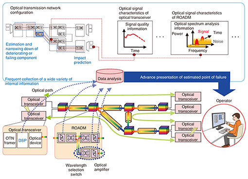
4. Activities to upgrade operations and maintenanceAs the capacity of optical transmission networks soars, the impact of optical transmission device failures increases. Even when optical signal quality degradation occurs, causing communication errors in the optical transceivers at both ends of the optical path, ROADM may not be able to detect anomalies if the anomaly exists in an optical amplifier or one of the wavelength-selective switches that constitute the ROADM in the relay section of the optical path. In such cases, the system component that caused the quality degradation may not be promptly pinpointed from a wide range of suspect components, and it may take a long time to restore the network. Therefore, we are seeking to detect failure signs and identify a suspect component with a high level of accuracy by collecting and analyzing detailed information about optical signal characteristics, which has not been fully used in conventional operations and maintenance. We are focusing on the following three types of optical signal characteristics: (1) Optical input/output power: Conventionally, optical power could be monitored only at 15-minute intervals. We will measure this information at shorter intervals and collect it in real time for use in failure analysis. (2) DSP internal state: We will start to collect and analyze data from DSPs—which compensate for optical signal degradation in the optical transceiver and execute demodulation—regarding optical signal intensity, noise level, and waveform distortion. (3) Optical spectrum: We will also start to collect and analyze optical signal-to-noise ratios inside the ROADM at each relay section. We are studying how to link such characteristic information with the optical transmission network configuration information, including the accommodation of optical paths. The aim is to accurately identify signal-degrading components that may lead to failure (Fig. 3) and, based on the time-series variation in the characteristics of the signal-degrading component, predict when the degradation will begin to impact the service [6].
5. ConclusionThis article introduced research and development efforts toward early practical implementation of the APN, focusing on the next-generation optical transmission network, which will serve as an advance release of the APN. With the aim of delivering low-power, high-quality, high-capacity, and low-latency optical transmission networks, we will continue our efforts to incorporate and engineer the APN’s elemental technologies, perfected at our laboratories, for system integration at the appropriate time. References
|
|||||||||||||||||||||||


