|
|||
|
|
|||
       |
Practical Field Information about Telecommunication Technologies Vol. 21, No. 12, pp. 55–59, Dec. 2023. https://doi.org/10.53829/ntr202312pf1 Case Studies in 50-bit/s Leased Lines: Modem Communication Failure at Earth-return Circuit and the Cause of Failure to Replace Metallic Transmission Line with Optical CableAbstractThis article introduces two failure cases concerning 50-bit/s leased lines: communication failure at the earth-return circuit and the cause of failure to replace a metallic transmission line with an optical cable due to the wrong selection of 50-bit/s leased line systems. This is the seventy-ninth article in a series on telecommunication technologies. Keywords: leased line, metallic-return circuit, earth-return circuit
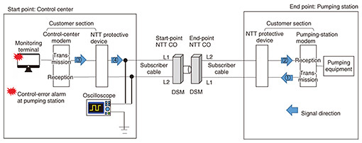
1. IntroductionA leased line is a dedicated network service that provides exclusive communications between specific customer premises. Leased lines offer higher quality and strict security compared with a public switched network or other network services and are widely used to connect internal lines between customer premises. Various companies use leased lines for monitoring or controlling various equipment as social infrastructures. Leased line services provided by NTT EAST/WEST are available for analog and digital communications. For analog communications, there are two types of low-speed services, those that transmit voice signal services and those that are modem or facsimile signal services. Modem or facsimile signal services are used for data transmission at minimum speeds as 50 bit/s. This article presents two failure cases in which the Technical Assistance and Support Center (TASC), NTT EAST, provided support for 50-bit/s leased lines: modem communication failure at the earth-return circuit and the cause of failure to replace a metallic transmission line with an optical cable. 2. Case studies2.1 Communication failure between sewage-treatment plants2.1.1 Equipment configuration and failure detailsThe first case is concerning a sewage-treatment company that uses a 50-bit/s leased line to monitor and control their pumping stations around the city. When a problem occurs in their system and they detect a control-error alarm from a specific pumping station, they sometimes inquire whether NTT’s leased line is operating normally. For such a claim, the NTT local maintenance center tried to detect the fault point in the leased line by changing the wire of the subscriber cables between the control center and pumping station. The NTT local maintenance center also replaced subscriber-line cards installed in the dedicated service-handling module (DSM), which accommodates leased lines at NTT central offices (COs). However, when the failure was not mitigated, the control center consulted TASC. In this case, the customer is using 50-bit/s leased line with earth return. The configuration of the customer’s system and NTT network (leased line) are shown in Fig. 1. To identify the cause of the failure, it is important to clarify the type of leased line. NTT generally provides two types of transmission methods for 50-bit/s leased lines: metallic return and earth return. A metallic-return method involves making a closed circuit with two wires in the line, and the direction of the current identifies the transmission and reception. An earth-return method involves making a closed circuit of a cable and ground (earth) with a unidirectional line used for transmission and the other for reception.
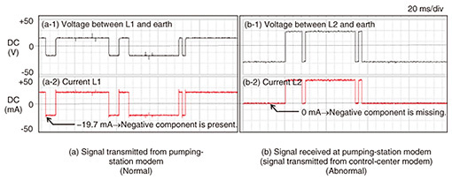
2.1.2 Investigation method for failure-factor inspectionWe assumed that the control-error alarm in the customer’s equipment was caused by an error in the communication signal. We first decided to investigate the voltage and current waveform conditions of the transmission signal between the DSM and customer’s equipment. We used an oscilloscope to measure the voltage and current of the modem signals, as shown in Fig. 1, at the control center and pumping station. Since this customer’s leased line using an earth-return method, we measured the signal voltages between L1-earth/L2-earth (2.1.3 (A)). We also measured the electrical characteristics of the on-premises wiring (NTT section and customer section) in the control center and pumping station (2.1.3 (B)). 2.1.3 Results of the investigation(A) Waveform of transmitted and received signals The measured waveform of the transmitted signal from the pumping-station modem (transmitted signal) and received signal from the control-center modem (received signal) are shown in Figs. 2(a) and (b), respectively. The transmitted signal (Fig. 1 Signal direction①) is formed using a bipolar encoding (i.e., 0 and 1 expressed as positive and negative) for both voltage and current (Fig. 2(a-1, a-2)); however, the received signal (Fig. 1 Signal direction②) is formed using a unipolar encoding (0 and 1 expressed as positive and 0A) with the negative component missing (Fig. 2(b-2)).
On the basis of these results, we concluded that the control-center modem was transmitting a normal bipolar encoding signal. However, before reaching the pumping-station modem, the transmitted current signal degraded to a unipolar encoding signal (Fig. 3).
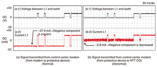
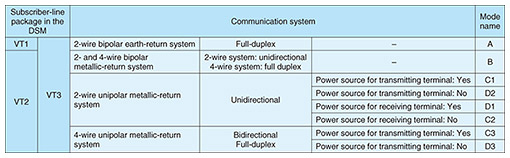
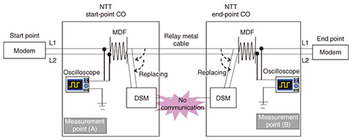
(B) Electrical characteristics of subscriber-lines (copper-impairment test) To confirm the normality of the metal wiring section, we also measured the electrical characteristics of subscriber-lines, i.e., foreign voltage, capacitance, and insulation resistance. The measurement results were within NTT’s maintenance standards at both the start and end points, and the section from the NTT CO to the NTT protective device was normal. Considering the results presented in sub-section (A), the control-error alarm was caused between the control-center modem to the NTT protective device; therefore, we measured the electrical characteristics, including the customer section (the customer modem to the NTT protective device) at the control center. From those measurement results, the insulation resistance between L1 and earth was nearly 0 Ω; in other words, L1 was in the earth-fault state within the customer section. 2.1.4 Cause of failureAfter identifying the suspected failure section, the NTT protective device and control-center modem were wired directly to bypass the other customer’s equipment. Thus, the control-error alarm no longer occurred. As a result of the customer’s equipment inspection of the private wiring section, it was confirmed that the customer’s arrester (surge arrester) inserted in this section was defective. 2.1.5 ConclusionThis case was not caused by NTT equipment failure but the customer’s equipment. The customer’s arrester installed in the customer section was broken, and L1 was connected to earth, which caused the signal transmitted from the control center to leak into earth. The pumping-station modem (on the receiving side) was thus unable to recognize that signal; therefore, the control-error alarm occurred at the control center. 2.2 Communication failure after replacing metallic transmission line with optical cableThe second case study concerns the line-replacing failure of a 50-bit/s leased line. 2.2.1 Equipment configuration and failure detailsIn this case, a 50-bit/s leased line is used to transmit data between the customer’s sites. The line connection between the two NTT COs which accommodate a 50-bit/s leased line is a metallic transmission line. We decided to eliminate the metallic transmission line and replace it with an optical cable using DSMs. There are various types of 50-bit/s leased line systems, as listed in Table 1, and different subscriber-line cards are used for each type. The results of an interview with the customer revealed that they were using an earth-return/unidirectional communication system for their terminals, so the NTT local service center member selected the VT1 package as the line card and replaced the line. However, a communication failure occurred. Thus, TASC was asked to investigate the cause of the failure. The configuration of the equipment involved in this case study is shown in Fig. 4.
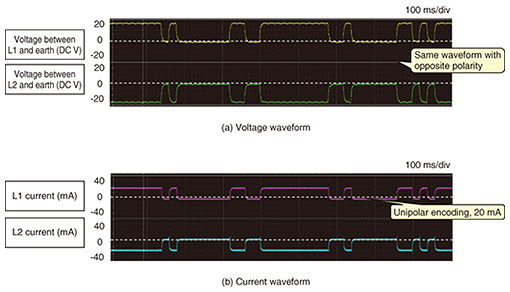
2.2.2 Investigation methodThe cause of the communication failure after replacing the DSMs may have been a mismatch between the communication modes of the customer’s modem and subscriber-line package. There are many setting patterns for the communication mode of a 50-bit/s leased line, and the operation mode must be set correctly after confirming the customer’s modem communication mode. On the basis of the above, we believed that it was necessary to confirm the operation mode on the basis of the facts, and as in case (1), we measured the communication signal using an oscilloscope. 2.2.3 Results of the investigation(A) Communication mode and encoding scheme The measurement results are shown in Fig. 5. The voltage waveforms on L1 and L2 had opposite polarity (Fig. 5(a)), indicating that the modems use the metallic-return system. Moreover, the code polarity of both voltage and current did not change, indicating that the encoding scheme is a unipolar encoding with a current of 20 mA (Fig. 5(b)).
(B) The state of transmitting-terminal power supply For proper selection of operation mode of a modem, it is necessary to check whether the transmitting terminal has a power source. Accordingly, we disconnected the lines and used an oscilloscope to measure the voltage between L1 and L2 at the start point and end point. We found it was −50 V at the start point and 0 V at the end point, which confirmed that the transmitting terminal has a power source. 2.2.4 Cause of failureConsidering the above results, we concluded that the customer’s 50-bit/s leased line differs from that stated in the information initially provided by the customer; the line uses a unidirectional 2-wire unipolar metallic-return system with a transmitting terminal having a power source. The VT2 or VT3 package should be used for this system, and operation modes should be C1 for the start point and C2 for the end point (Table 1). 2.2.5 ConclusionOn the basis of the above findings, communication failure was resolved when C1 and C2 selected the subscriber-line VT3 package. Since the metallic transmission line could be replaced with an optical cable, the metallic cable between the start-point and end-point COs could be eliminated. 3. Concluding remarksThis article introduced two failure cases in a 50-bit/s leased line: modem communication failure at the earth-return circuit and the cause of failure to replace a metallic transmission line with an optical cable. It is important to measure the waveform using an oscilloscope effectively to analyze 50-bit/s leased lines. The Network Interface Engineering Group of TASC provides technical support for early resolution of problems with equipment, terminals, and networks by acquiring and analyzing data by using various tools. We will continue to disseminate technologies by providing technical support, developing tools, and holding technical seminars. |
||