|
|||||||||
|
|
|||||||||
       |
Practical Field Information about Telecommunication Technologies Vol. 22, No. 8, pp. 43–47, Aug. 2024. https://doi.org/10.53829/ntr202408pf1 Extending Usability of Copper Cables Installed Underground by Using a Cable-retracting SystemAbstractThe Technical Assistance and Support Center (TASC), NTT EAST developed a cable-retracting system for pulling underground copper cables that have moved back into their proper position. This article introduces this system and describes efforts to extend the usability of installed copper cables by using it. This is the eighty-third article in a series on telecommunication technologies. Keywords: copper cable, cable-retracting system, underground conduit
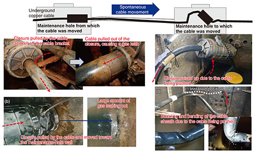
1. IntroductionCables for providing telecommunication services are installed in underground service tunnels, conduits, maintenance holes, and on utility poles above ground. Some copper cables installed in underground conduits may spontaneously move from the installed position over time due to vibration and other effects from vehicles traveling on the road directly above. This outcome is particularly pronounced around roads located on soft ground and on which many heavy vehicles travel. If a cable has moved significantly from its original position, it has been necessary to remove the cable and install a new one. To solve such a problem, the Technical Assistance and Support Center (TASC), NTT EAST developed a cable-retracting system for pulling moved underground copper cables back into their proper position without having to replace them, thus extending the usability of the cables. This article introduces this system and describes efforts to extend the usability of installed copper cables using it while responding to various situations involving cable movement across Japan. 2. Effects of cable movement on surrounding facilitiesWhen a cable installed in an underground conduit spontaneously moves from its proper position, tension in the cable due to pulling or overlength of the cable due to pushing occurs in the maintenance holes on each side of the conduit housing the cable (Fig. 1). Specifically, spontaneous cable pulling and pushing can cause the following problems in maintenance holes: a closure (i.e., cable-connection point) falls off the cable bracket due to the cable being pulled (Fig. 1(a)), a closure contacts the wall of the maintenance hole due to the cable being pulled toward the conduit (Fig. 1(b)), the position of a closure changes due to the overlength of the cable being pushed (Fig. 1(c)), and a cable buckles due to the cable being significantly pushed (Fig. 1(d)).
If these problems concerning underground copper cables occur, they will lead to leakage of the dry air (hereinafter referred to as gas) sealed inside the cables and closures for the purpose of maintenance*1; thus, immediate measures need to be taken.
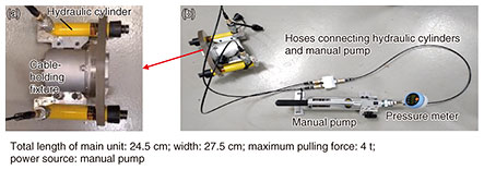
3. Purpose of developing cable-retracting systemThe conventional method or removing a spontaneously moved cable and installing a new one is extremely costly. To avoid such cable reinstalling and enable the continued use of cables, we developed a cable-retracting system for pulling moved cables back into their original position. We also conducted trials in the field where cable movement has occurred across Japan. The results of those trials have confirmed the effectiveness of the system. 4. Overview of cable-retracting systemThe cable-retracting system consists of a main unit (Fig. 2(a))—which is composed of a fixture for preventing spontaneous cable movement that holds the cable for retracting (hereafter cable-holding fixture) and two hydraulic cylinders—as well as a pump-connection hose, pressure meter, and manual pump (Fig. 2(b)). The hydraulic cylinders are bolted to the side of the cable-holding fixture and connected to the manual pump via the pump-connection hose. The mechanism for retracting the cable involves the following steps: when the manual pump is operated, pressure is applied to the hydraulic cylinders, and the internal rod of each cylinder extends and pushes the cable-holding fixture away from the maintenance-hole wall. Thus, the cable is pulled.
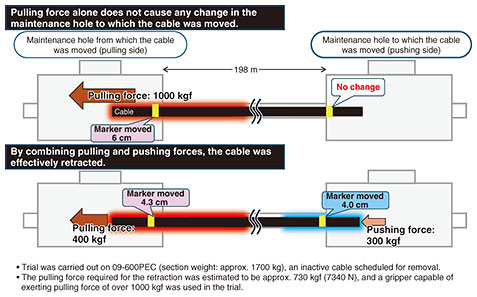
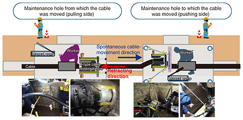
During a trial conducted at an actual facility, we found that simply pulling the cable from the maintenance hole from which it was moved (pulling side) is not enough, because it only stretched the cable inside the conduit and did not move the cable. In addition to the pulling force, we thus added a force to “push” the cable into the conduit from the maintenance hole to which the cable was moved (pushing side). This combination of pulling and pushing forces enabled retracting long, heavy cables while simultaneously reducing the physical load on the cable by making it possible to retract the cable with less pulling force (Fig. 3).
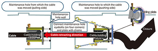
An illustration of installation when a pulling device is combined with a pushing device is shown in Fig. 4.
To push the cable from the maintenance hole to which it was moved, a strong pushing plate is installed behind the pushing device attached to the cable. The mechanism for pushing the cable is the same as that for pulling it; namely, the rod of each hydraulic cylinder extends and pushes the cable-holding fixture away from the plate. This action pushes the cable back into the conduit. The pushing plate is secured to the eye bolts on the four corners of the maintenance-hole wall by chains. 5. Operation of retracting a cableRetracting a cable is done by the pulling side, assisted by the pushing side (ratio of pulling force to pushing force: 2:1 to 1.5). As shown in Fig. 5, the worker on the pulling side and worker on the pushing side communicate by mobile phone and cooperate in gradually retracting the cable.
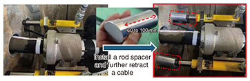
The cable-holding fixture exerts a gripping force of up to 6000 N (611.8 kgf), and we confirmed that when a force exceeding that is applied, the gripping part of the fixture begins to slip so that the cable will not be damaged due to the pulling force exceeding the allowable tension of the cable. 6. Other components for assisting in retracting a cable(1) Rod spacer The length of the rods extending from the hydraulic cylinders of the cable-retracting system is a maximum of 12.6 cm. When it became necessary to retract the cable further than this length, the pulling and pushing devices were detached from the cable, the devices were reattached, and retracting was resumed. To streamline this process, we developed a dedicated rod spacer (Fig. 6). Attaching the rod spacer between the rod and maintenance-hole wall makes it possible to retract the cable longer than 12.6 cm, shortening the time it takes to detach and reattach the pulling and pushing devices.
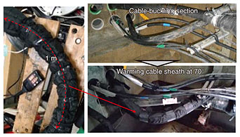
(2) Cable warmer Cables that have been deformed over a long period due to cable movement and moved closures must be positioned in the proper location where they will not interfere with maintenance work. When a cable that was severely bent (buckled) is retracted, the buckled part of the cable needs to be straightened and returned to its original shape in accordance with the amount of retracting. However, this straightening cannot be done by human force, and the strong pulling force of the cable-retracting system could damage the cable sheath. A cable warmer is therefore wrapped around the buckled part to locally heat and soften it so that it can be returned to its original shape and repaired (Fig. 7).
7. Support for retracting cables nationwideBy using the cable-retracting system, we repaired moved cables in 14 locations and 26 sections*2 nationwide, thus succeeding in extending the usability of the copper cables installed underground. The results of our nationwide survey indicate cables have moved in many locations; thus, it is necessary to establish the conditions and mechanisms to enable on-site maintenance personnel to restore those cables. We are currently creating an operation manual and arranging the rental of the cable-retracting system. We are also conducting a trial to verify the removal of copper cables, including lead-covered cables (which are difficult to remove), from underground sections by using this system.
8. ConclusionWe introduced a cable-retracting system we developed to solve the problem of moved underground copper cables. We also described efforts to extend the usability of installed copper cables by pulling and pushing a moved cable at the maintenance holes on each side of the conduit housing it by using this system. At TASC, we will use our accumulated knowledge, experience, and new technologies to provide technical support to resolve difficult-to-solve failures of access equipment and facilities that occur in the field across Japan. We will also continue our efforts to prevent gas leaks caused by movement of underground copper cables, the only solution to which had been replacing the cable. Reference
|
||||||||