|
|||||||
|
|
|||||||
       |
Regular Articles Vol. 23, No. 9, pp. 56–62, Sept. 2025. https://doi.org/10.53829/ntr202509ra2 Optical-fiber Cables for On-road Surface Wiring without Using Poles and ConduitsAbstractThe NTT Group is investigating further coverage expansion of optical-fiber networks for 5G (fifth-generation mobile communications network) base-station demand and popularization of Internet-of-things devices. NTT has thus developed an on-road surface-wiring optical-cable technology that does not depend on utility poles or underground conduits, which has been essential for optical-cable installation. It also allows for optical-fiber cables to be laid without the need for large-scale construction such as road excavation. This article gives an overview of this technology, which enables road-surface wiring by installing optical-fiber cables in grooves formed on asphalt pavement. Keywords: optical-fiber cable, road surface, cable wiring
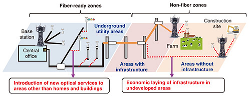
1. Challenges with optical-cable-laying technologyInstalling optical-fiber cables for telecommunications requires either constructing conduits and maintenance holes underground as foundational infrastructure to protect the cables or erecting utility poles above ground for cable installation. Constructing underground conduits, in particular, necessitates road excavation, which is a large-scale undertaking requiring road-occupancy procedures and traffic regulations during the construction period. However, with the spread of Internet-of-things (IoT) devices and the development of fifth-generation mobile communications network (5G) base stations, future optical communications will need to respond flexibly and swiftly to new demands in urban areas where utility poles have been removed, suburban areas without infrastructure, farms, and construction sites (Fig. 1).
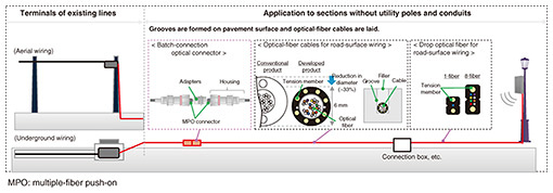
In mountainous areas, for example, where there are no utility poles or other facilities, it is necessary to construct new utility poles and lay optical-fiber cables a long distance to the service site. However, there are places in national and quasi-national parks where it is difficult to erect utility poles from the viewpoint of landscape protection, and it is necessary to carry out large-scale road-excavation work to construct underground conduits over long distances to provide optical fibers there with conventional technology. In urban undergrounded utility areas where utility poles have been removed, if new optical-fiber cables need to be installed for streetlights, ground transformers, public telephone booths, etc. and the existing conduits cannot be used due to a fault or other reason, large-scale construction work is required to open and cut the road in the area. In such cases in urban areas with heavy traffic, there are many restrictions, such as not being able to easily obtain road-construction permission to construct a new conduit or being allowed to construct a new conduit only at midnight, making it difficult to lay optical-fiber cables. Therefore, there is a need for technology for quickly and easily laying optical-fiber cables at low cost without the need to construct infrastructure such as conduits and utility poles. 2. Optical-cable technology for on-road surface wiringThe optical-cable technology for on-road surface wiring we developed eliminates the need for constructing the infrastructure necessary for laying optical-fiber cables, and by laying the optical-fiber cables in a groove constructed on the asphalt road surface, it is possible to construct the optical-fiber infrastructure quickly and at low cost. Figure 2 shows our on-road surface-wiring optical-cable technology. Optical-fiber cables are efficiently constructed up to mobile base stations, etc., by forming grooves on the road surface using commercially available road cutters and laying optical-fiber cables for road-surface wiring in these grooves (Fig. 3). Since optical-fiber cables can be connected to each other using a batch-connection connector, the optical-fiber networks can be flexibly constructed in a short time without installing the closure. To draw optical-fiber cables into base stations, it is possible to branch the drop optical fiber for road-surface wiring from the optical-fiber cable for road-surface wiring by installing a simple connection box formed on the road surface or a thin closure for road-surface wiring.
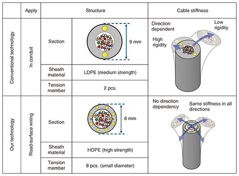
2.1 Basic structure of components used in our on-road surface-wiring optical-cable technologyThe optical-fiber cable used in our on-road surface-wiring technology is designed to have an outer diameter of about 6 mm because the blade of a general-purpose road cutter used in road construction is about 8 mm. To mount optical-fiber cores of up to 40 fibers on a cable of this size, we used high-density polyethylene (HDPE), which has higher rigidity than conventional low-density polyethylene (LDPE), for the outer sheath of the cable to achieve both strength and small diameter [1]. When wiring is placed on a road surface, not only bending in the horizontal direction but also bending in the vertical direction to exceed the level difference is required. Therefore, eight tension members with a smaller diameter than conventional ones are arranged circumferentially in the sheath to fabricate a flexible cable with a smaller diameter and no directional dependence on the bending of the cable while maintaining the same mechanical properties as conventional cables. Table 1 shows a comparison between the conventional and our technologies.
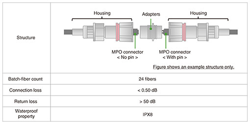
The batch-connection optical connector shown in Table 2 consists of a 24-fiber multiple-fiber push on (MPO) connector, adapter, and housing, enabling the simultaneous connection of up to 24 optical fibers. Connecting optical-fiber cables traditionally required attaching a closure and repeatedly fusion-splicing the optical-fiber strands, typically four strands (one fiber ribbon) at a time, before housing them in the closure. However, our technology enables easy connection by fitting the connectors together without using tools and connection between optical-fiber cables in a short time. Considering that our technology can be used on a road surface, it is equipped with waterproofing to ensure quality even during long-term flooding due to heavy rain.
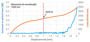
The drop optical fiber for road-surface wiring used for installing optical-fiber cables into base stations and other facilities has a maximum of eight optical-fiber strands, similar to aerial drop optical fibers, and their shapes are the same as those of such fibers. This makes it possible to use field-assembly connectors, optical cabinets, etc., without creating new materials or developing methods. 2.2 Characteristics required for road-surface-wiring technologyThe pavement surface on which a cable is laid expands and contracts due to temperature change. Considering that the asphalt modulus of the paved road surface is more than one order of magnitude higher than that of the optical-fiber cable, the optical-fiber cable is forced to change, so the cable-lateral pressure is required to withstand a constant displacement [2]. The amount of expansion and contraction of the entire road surface due to temperature expansion and contraction is calculated using the following formula. Δd > K × D × ΔT, where K is a coefficient of linear expansion, D is the road width, ΔT is temperature change, and Δd is the road-surface-deformation variation. The ΔT is set to 50°C on the basis of room temperature. The calculations show that the expansion and contraction of the entire road surface is approximately 5 mm. With this technology, the depth of the formed grooves is kept to the middle of the asphalt layer on the pavement surface so that the grooves and asphalt layer as a whole will be affected by temperature changes. The effect of road-surface expansion and contraction is also limited due to the grooves, thus reducing the forced displacement from the road surface. Although the impact of road-surface expansion and contraction due to this groove width is less than 0.1 mm from the above equation, we designed the optical-fiber cable to be immune to such road-surface movements by ensuring it can tolerate up to 1 mm of deformation pressure without affecting its performance. To fabricate a cable with a small diameter that is not subjected to forced displacement from the road surface, we used HDPE as the sheath material and eight small-diameter aramid fiber reinforced plastics as the tensile-strength material to develop a small-diameter, flexible, and easy-to-lay optical-fiber cable that can withstand forced displacement from the road surface. We conducted a cable-compression test on the newly developed optical-fiber cables, simulating forced displacement from the road surface. Figure 4 shows the measurement results for displacement, load, and optical loss. The increase in optical loss at 1 mm of displacement was 0.05 dB or less per optical-fiber strand, demonstrating that forced displacement from the road due to temperature contraction does not affect the cable’s characteristics. The load at this point was 1670 N/mm.
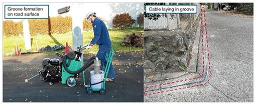
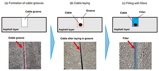
2.3 Method for constructing road-surface wiringThe method for constructing road-surface wiring consists of four steps: (a) forming the groove, (b) laying the cable in the groove, and (c) filling the groove with a filler (Fig. 5).
When forming grooves on the road surface, marking is first carried out with chalk powder or similar material where grooves are to be formed. Along the marked portion, a general-purpose road cutter is next used to cut and form a groove for laying the cable. The width of the groove to be formed is 8 mm in consideration of the thickness of the general-purpose cutter blade. The depth is about 20–30 mm. A cable is then laid in the formed groove. For delivery from a cable drum, the drum roller used for laying overhead and underground cables is used to carry out the delivery work. Finally, for protecting the cable laid in the groove, a filler used in general road-repair work is used to fill in the groove. No special tools or construction machinery are required for the installation. The road cutter used is a commercially available construction machine also used for road excavation during conduit construction, enabling installation with tools and construction machinery typically used in conventional infrastructure construction. While this article focused on construction in straight sections, construction in curved sections can also be carried out using another general-purpose road cutter. 3. Future prospectsWe introduced our on-road surface-wiring optical-cable technology and its construction method, which enables the laying of optical-fiber cables on a road surface without depending on basic facilities such as utility poles and conduits. To promote the development of IoT and 5G base stations, it is necessary to provide optical-fiber networks in a finely tuned manner to locations that have been difficult to provide with conventional technologies. With this technology, the construction of infrastructure equipment requiring large-scale construction becomes unnecessary, and optical fibers can be delivered flexibly in a short time. NTT will continue to further expand the coverage of its optical-fiber network. References
|
||||||