|
|||||||
|
|
|||||||
       |
Practical Field Information about Telecommunication Technologies Vol. 23, No. 11, pp. 90–94, Nov. 2025. https://doi.org/10.53829/ntr202511pf1 Countermeasures to Lightning Damage for Outdoor-installed Optical Access Equipment (RSBM-F)AbstractThis article presents an example of a failure of an RSBM-F (remote subscriber module feeder point), outdoor-installed optical access equipment, due to lightning surges and countermeasures taken against such failure. Keywords: lightning surge, RSBM-F, surge arrester
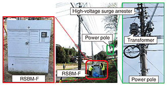
1. IntroductionOutdoor telecommunication and power equipment is susceptible to various natural disasters. As climate change progresses, lightning strikes have been increasing. Countermeasures against lightning surges entering telecommunication equipment are thus becoming essential. One type of telecommunication equipment installed outdoors is a piece of optical access equipment for remotely housing analog and/or ISDN (integrated services digital network) lines called a remote subscriber module feeder point (RSBM-F). Since an RSBM-F is supplied with commercial 100-V power and houses metal communication lines, lightning surges caused by lightning strikes can propagate into the RSBM-F through both the power and/or communication lines. An example of a failure of outdoor telecommunication equipment due to lightning damage, namely, single-path failure of the power-supply unit of an RSBM-F, and countermeasures taken against such failure are introduced in this article. 2. Example of failureDuring a thunderstorm, single-path failure of the power-supply unit of an RSBM-F repeatedly occurred. This power-supply failure was the alarm being triggered when either the rectifier package in the power-supply unit of an RSBM-F failed or the breaker mounted in the rectifier tripped. A maintenance person visited the RSBM-F site and confirmed that the failure was not the problem of the rectifier package of the RSMB-F but the tripping of the breaker. As this failure had occurred repeatedly, we at Technical Assistance and Support Center, NTT EAST (TASC) were asked to investigate the cause of the failure and propose countermeasures. 2.1 Installation status and RSBM-F configuration at the time of failureThe installation status of the RSBM-F is shown in Fig. 1. The RSBM-F is located in a non-urban area with no tall buildings or other facilities nearby that would be directly affected by lightning strikes. A power pole equipped with a high-voltage surge arrester and transformer is located about 100 meters from the installation location of the RSBM-F.
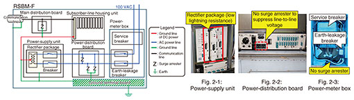
The internal configuration of the RSBM-F that was investigated on-site is shown in Fig. 2. Although the RSBM-F has a standard configuration, from the perspective of lightning-damage prevention, we observed the following three improvement points.
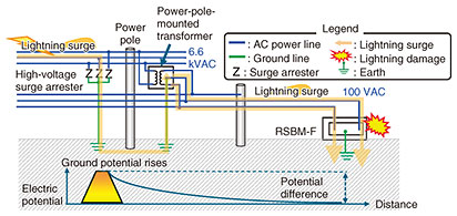
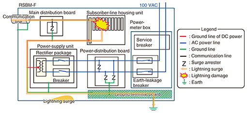
For these three reasons, we proposed that the configuration of the RSBM-F require additional countermeasures against lightning surge. 2.2 Estimation of cause of failureThe propagation route of a lightning surge is shown in Fig. 3. Lightning-occurrence data at the time of the failure of the RSBM-F showed no lightning strikes occurred within a 1-km radius of the RSBM-F. Considering the relative positions of the RSBM-F and the power pole, we estimated that a lightning surge was induced in the pole’s high-voltage power lines and flowed through the high-voltage surge arrester on the power pole to the ground where the surge increased the ground potential [1] around the pole. The increased ground potential then caused the lightning surge to flow back up to the ground line of the power-pole-mounted transformer, propagate along the low-voltage power lines, and reach the RSBM-F.
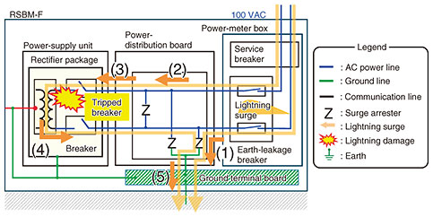
The propagation route of a lightning surge on the power line of the RSBM-F is shown in Fig. 4. The lightning surge entered the RSBM-F through the power line and propagated through the power-meter box and power-distribution board to the rectifier package in the power-supply unit where it tripped the breaker. The power-distribution board was equipped with surge arresters to prevent lightning surges between line-to-line and between line-to-ground; however, we assumed that the lightning surge propagated to the rectifier package as the surge arresters operated as follows:
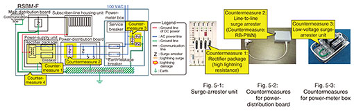
2.3 Countermeasures against lightning-surge failureThe countermeasures taken for protecting the RSBM-F against lightning surge are shown in Fig. 5. To prevent this lightning-surge-induced failure of the RSBM-F, it is necessary to satisfy two requirements: (i) increase the lightning-surge resistance of the rectifier package in the power-supply unit and (ii) suppress the line-to-line voltage caused by the one-side operation of the surge arresters in the power-distribution board.
In preparation for the occurrence of higher-voltage lightning surges than that for this failure, installing surge arresters in multiple stages to drain the lightning surge gradually to the ground is also needed. The following three countermeasures were implemented to prevent lightning surges from entering the RSBM-F through power lines. Countermeasure 1: Replace the rectifier package with one that is more resistant to lightning The rectifier package installed in the RSBM-F was replaced with a package with improved lightning resistance (Fig. 5-1). This countermeasure enables the package to withstand a certain level of lightning surge. Countermeasure 2: Install a surge arrester in the power-distribution board to suppress line-to-line voltage A line-to-line surge arrester (countermeasure product: RB-PWN [2] manufactured by Nisshin Electric Co., Ltd.) was installed (Fig. 5-2). This arrester directs lightning surges that would otherwise propagate to the power-supply unit to the ground. Countermeasure 3: Install a low-voltage surge-arrester unit in the power-meter box Low-voltage surge arresters were connected between the power lines and between the power lines and ground line in the power-meter box, and the ground line was connected to the ground terminal board of the RSBM-F (Fig. 5-3). This configuration reduces lightning damage by directing a large lightning surge that enters the RSBM-F from the power lines to the ground. As a result of implementing the above three countermeasures, lightning-surge-induced failure of the RSBM-F no longer occurred. 2.4 Additional countermeasuresAlthough lightning surges entering through communication lines were not the cause of the failure, it is also necessary to prevent possible failures caused by such lightning surges. The propagation route of a lightning surge that enters the RSBM-F through the communication line is shown in Fig. 6. We assumed that a lightning surge that penetrates the communication line will propagate through the main distribution board to the subscriber-line housing unit and damage the subscriber-line packages. It then flows out through the −48-VDC (volts direct current) ground line to the ground terminal board connected to the power-supply unit. The specific countermeasure taken against this type of communication-line lightning-surge damage is as follows.
Countermeasure 4: Install a ground line between the main distribution board and ground terminal board of the RSBM-F A new ground line was installed between the main distribution board and the RSBM-F’s ground terminal board (Fig. 5). This countermeasure allows for lightning surges penetrating from the main distribution board to flow to the ground, reducing lightning surges entering the subscriber-line housing unit. 3. Concluding remarksAn example of lightning-surge-induced failure of an RSBM-F and countermeasures for such failure were introduced in this article. TASC will continue contributing to solving on-site problems through technical support for those involved in the maintenance and operation of telecommunication facilities. References
|
||||||