|
|||||||||||||||||||||||||||||||||||||||||
|
|
|||||||||||||||||||||||||||||||||||||||||
       |
Vol. 5, No. 11, pp. 25–32, Nov. 2007. https://doi.org/10.53829/ntr200711sf4 Human Pose Estimation for Image MonitoringAbstractWe introduce human pose estimation techniques based on image processing. These techniques can detect suspicious human behavior. They can also be used for designing effective product displays in shops by subjecting the points of customer interest to aggregative analysis. This article describes two estimation techniques that use one camera and multiple cameras, respectively. 
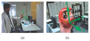
1. IntroductionThe need for monitoring systems is increasing due to changes in social conditions. In particular, the application of intelligent processing functions to the monitoring of images is expected to yield services such as the detection of suspicious human behavior and effective product display design in shops. These functions require techniques for detecting humans in images, the direction in which they are facing, and their body poses. These are collectively called human pose estimation techniques. While real humans are three dimensional, the image captured by a monitoring camera is two-dimensional (2D). The key to human pose estimation is the question of how the three-dimensional (3D) state can be estimated from 2D information. Human pose can be estimated by movement differentiation and can be roughly categorized into two types. One type is the pose and direction of the head. The information available in a sequence of images mainly consists of 3D rotations, i.e., yaw, roll, and pitch. Other changes such as changes in facial expression are relatively small. The other type, body pose, is indicated by region state information such as a limb position, and elbow and knee flexions. This information includes not only 3D rotation, but also complicated changes arising from elbow and knee movements. In this article, we first describe two methods (Fig. 1) that are appropriate for estimating these two pose types. Head pose estimation is achieved by 2D matching between a practical monitoring image and stored face images that are captured in advance by a single camera from all directions. Body pose estimation is achieved by regenerating a 3D human image from images captured by multiple cameras. 2D matching can estimate only the face direction, but its costs are low. 3D regeneration can estimate the entire body state, but its costs are high. One of these two methods should be selected depending on the situation envisaged. Second, we describe a sophisticated 3D figure acquisition method that can estimate the face pose from a single-camera input and estimate the body pose from multiple cameras.
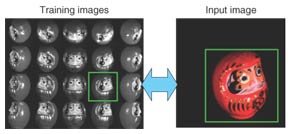
2. Face pose estimation using single-camera input2.1 OverviewMethods that can estimate object pose from the images captured by a single camera have a very broad range of applications. Many estimation algorithms have been proposed [1]–[3]. We have devised a practical algorithm from a similar point of view. In this section, we describe an experiment on face pose estimation and present its results. The basic concept of our method is shown in Fig. 2. Face pose is estimated by determining the best match between the input image and images stored in a database. This method, however, has two disadvantages: a huge amount of memory is required to implement the basic concept and matching takes too long. To eliminate these drawbacks, we are studying a new matching method that has a function that approximates the relationships between the image and pose parameters (yaw, roll, and pitch) by utilizing two statistical methods at the same time: principal component analysis (PCA) and support vector regression (SVR) [4].
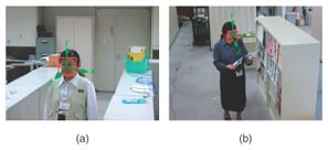
2.2 SVR-based approachThe method is composed of the training process and the pose estimation process. In the training process, an eigenspace is derived from the training vectors, which are images of the same 3D object in various poses. Typical training images are shown in Fig. 2. The pose estimation functions are derived from the training vectors projected to the eigenspace by using SVR. In the pose estimation process, an input vector is projected into the eigenspace. If the projected vector is fed into the pose estimation functions, the values of the pose parameters are output. The eigenspace is derived from the group of training image samples by using PCA. First of all, the intensities of all pixels in each image sample are raster scanned, and the set of values is taken as a vector. Next, each vector is normalized to make the norm of the vector equal 1. An average vector and a covariance matrix are calculated from the normalized vectors, and eigenvectors are computed by PCA. The subspace, which is composed of the 1st to the dth component vectors, is called the eigenspace. The value of d is much smaller than the number of image pixels and also the original number of dimensions. Pose estimation functions are derived as regression equations using SVR on the eigenspace. In this article, pose parameters are defined as yaw, pitch, and roll (hereinafter denoted by Y, P, R). Optimal regression coefficients are calculated to fit into a defined area called the ε-insensitive band by SVR. If a sample does not fit into the ε-insensitive band, a penalty is imposed according to the sample’s distance from the band edge. The penalty is minimized as much as possible. The pose estimation function is defined as 2.3 Algorithm robust against local occlusions and non-stationary backgroundsFurthermore, we add the following process in order to estimate the true pose even if the lighting conditions and background in the input image differ from those used when capturing the reference images or if the input image contains local occlusions [5]. This additional method extracts the modified gradient feature from images instead of the conventional image brightness pattern. This feature is, in part, generated by filtering the edge directions because such information is not influenced by changes in lighting or background. The other additional method is that pose estimation values are calculated in each independent area: the input image is divided into multiple areas. Our method selects the most relevant value from all area data. The weighted median value based on reliability is utilized in this selection step. The reliability is obtained by the degree of similarity with captured image patterns. Since the estimation value is ignored when the images are occluded, the estimation values calculated in non-occluded areas can provide appropriate pose parameters. Pose estimation results for the captured image in Fig. 2 are shown in Fig. 3. The estimated pose is indicated by 3D coordinate axes. The Z-axis indicates the direction in which the face is pointing. This figure demonstrates that the pose was estimated well. The human face pose estimation result output by this method is shown in Fig. 4. The human face direction is precisely estimated for the normal movements that appear in the monitoring image. In this experiment, images of the same person were used in the estimation process and used as the capture process. We believe that our method can be expanded to unspecified face pose estimation by a modification in which facial images of multiple persons are captured simultaneously.
3. Human body 3D shape regeneration by multiviewpoint cameras3.1 OverviewThe technique of 3D shape modeling from multi-viewpoint videos has recently become popular. 3D shape data of a moving person can be utilized to analyze human motion and understand human actions. First of all, we introduce our comprehensive motion analysis scheme for 3D body shape regeneration. The scheme contains the following three steps: 1. Multiviewpoint camera studio setup. In this step, the camera layout is determined and a synchronization mechanism is used to achieve the synchronized capture of the target from multiple viewpoints. The cameras are also calibrated in this step; the locations and the viewing directions of all cameras are accurately measured. 2. Wide-area 3D shape regeneration. While the 3D shape modeling technique has become popular, 3D shape regeneration of a moving person still faces several technical issues. Previous related studies used small areas for 3D shape regeneration, so it is difficult to obtain a 3D model of natural motion using them. We have developed an extended algorithm for wide-area 3D shape regeneration. 3. 3D skeleton extraction. In this step, by fitting reconstructed 3D shape data to a 3D skeleton model, we can get the motion parameters of each part of the body. Such motion parameters are obviously useful for motion analysis and action understanding. Among the above steps, 3D shape regeneration is the key technique, so we describe it in detail below. 3.2 Wide-area 3D shape regenerationWe use the silhouette volume intersection method [6], [7], [8], [11]–[13] as a basic computational algorithm to obtain the 3D shape of the object from multiview images (Fig. 5). This method is based on the silhouette constraint that a 3D object is encased in the 3D frustum produced by back-projecting a 2D object silhouette onto an image plane. With multiview object images, therefore, an approximation of the 3D object shape can be obtained by intersecting such frusta. This approximation is called the visual hull [10]. Recently, this method was further extended by using photometric information to reconstruct shapes more accurately [9].
3.2.1 Naïve algorithm for obtaining shape from silhouettesShape from silhouettes (SFS) is a popular method of obtaining a 3D shape. The naïve algorithm of SFS is described below. One frame of the silhouette observed by one of the cameras is shown in Fig. 6. Black represents the background and white the target. The gray polygon means the voxels projected on the screen. Let i be the camera index of the N-camera system, and let ν denote one voxel. For voxel v, let w(v) denote the occupation state of v. That is, if w(v) = 1, then v is occupied by the target; if w(v) = 0, then v is empty. This w(v) can be simply computed by the following equation.
Note that if v is projected out of the picture, wi(v) is defined to be 0, and the voxel is determined to be empty by Eq. (3).
3.2.2 Extension algorithm using partially observed silhouettesIt is clear that the limitation of the naïve SFS is due to the definition used in Eq. (4), where the state in which the voxel cannot be observed by the camera is not distinguished from the state in which the voxel is projected onto the background. Therefore, our algorithm introduces a representation to handle the “outside the field of view” case, as shown in Fig. 7. Adding the “outside” part to the definition means that we have a total of six different cases when projecting one voxel onto one camera screen. Three of the cases are shown in Fig. 8 and the other three are shown in Fig. 9. In addition to variable wi(v), we introduce oi(v) to represent whether or not v is observed outside the field of view. It is defined by the following equation.
According to this definition, for voxel v, if oi(v) = 1, it means that v is not entirely observed by the i-th camera. For the N-camera system, if First, we project voxel v to all N cameras. We then have the set {wi(v)|i = 1, 2, ..., N} and the set {oi(v)|i = 1, 2, ..., N}. Here, we define the set W(v) as Second, we define a reliable intersection function, w'(v) as where w'(v) is just the occupation result calculated by the cameras, where v is entirely observed. Introducing the threshold, T(v), lets us perform the final occupation computation as follows.
Note that the threshold is defined as a function of v. This means that the reliability of the system is location-sensitive. In practice, the reliability is determined by the camera layout. That means that if the cameras are fixed, for each voxel, the number of cameras that can completely observe the voxel can be calculated beforehand and the threshold can be determined from that number. The above extension has the effect, for each voxel, of filtering the camera output according to each camera’s field of view. As a result, there is no need for all cameras to fully observe all voxels forming the computation region. That is, full 3D shapes can be computed from partially observed silhouettes.
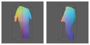
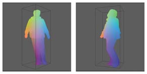
3.2.3 Fast target area detection using octree searching algorithmThe computation region for shape regeneration can be enlarged by applying the shape from the partial silhouette algorithm. Generally speaking, computation complexity increases as the region becomes large. To shorten the computation time, we use an octree-based search algorithm to detect the target area before conducting wide-area shape regeneration. In practice, we divide the entire space into cubes. The target area can then be defined as a subset of the total set of cubes. To find which cubes are within the target area, we use the octree searching algorithm. The processing flow, shown in Fig. 10, is well known, so details of the algorithm are omitted. Moreover, by preparing a multiresolution silhouette image pyramid, we can speed up target area detection even more. The results of the naïve SFS algorithm are shown in Fig. 11, where the head part of the person is excluded. Since not all of the cameras were configured to capture the full body of the person perfectly, we decided to exclude the head part. The results of our extended algorithm, when applied to the silhouette images from the same input, are shown in Fig. 12. These results prove the effectiveness of our extended algorithm.
4. ConclusionOur extension of the SFS algorithm yields truly effective multiviewpoint camera systems that offer 3D shape regeneration over wide areas. We have also developed a fast target area detection method based on the octree search algorithm. Experiments have demonstrated the effectiveness of the extended algorithm. 3D shape capturing systems such as these will enable the full-body shapes of moving people to be obtained and utilized for motion analysis. We are now developing a compact capture system that is easy to set up and are testing it in trials. In future, we intend to expand the technique by including advanced human behavioral analysis based on the pose information yielded by the basic technique. References
|
||||||||||||||||||||||||||||||||||||||||