 |
|||
|
|
|||
|
Letters Vol. 6, No. 10, pp. 25–30, Oct. 2008. https://doi.org/10.53829/ntr200810le2 Technique for Repairing Bridge-supported ConduitsAbstractWe have developed a technique for performing in-situ partial repairs on bridge-supported conduits that have cables running through them. The safe, inexpensive, and timely repair of corroded bridge-supported conduits is essential to improve the adaptability of optical services and prolong the lifetime of network installations. This article presents an overview of this new technique.
1. IntroductionMetal conduits that are supported by bridges are subjected to environments where corrosion can easily occur as a result of factors such as (1) the cyclical variations in humidity caused by precipitation and (2) the effects of airborne salt in coastal areas and places where roads are salted in winter to prevent freezing (Fig. 1). A corroded conduit could lead to the cables inside it being damaged or people getting hurt by it falling off the bridge. Consequently, there is a need for safe, simple, and low-cost repair techniques that can be used to perform permanent and effective repairs on corroded conduits.
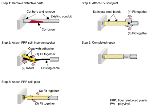
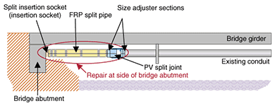
2. Existing repair techniques for bridge-supported conduitsNTT businesses possess roughly 11,000 kilometers of bridge-supported conduits in about 40,000 different locations. In fiscal year 2006, repairs were carried out on bridge-supported conduits in 1000 of these locations, including the repainting of conduits and metal fixtures. So far, repairs to conduits supported in the middle of bridges have been made using stainless steel split pipe structures, but as production lines become outdated, it is becoming harder to produce such parts and the need has arisen for substitute repair materials and repair techniques. Meanwhile, repairs next to the bridge abutments cannot be made using the standard repair method. Instead, they involve a major amount of work whereby the bridge abutment is partially broken away to allow a connection to be made to the non-corroded part of the conduit inside the concrete and the abutment is then restored. This method involves a considerable amount of time and expense. 3. New repair technique for bridge-supported conduitsThe new repair technique that we have developed is applicable to various situations, but they can be broadly divided into cases where it is applied at the side of bridge abutments and cases where it is applied in the midsection of a bridge. The same repair method is used for both types of repair. It involves cutting away the corroded and degraded parts requiring repair and then incorporating repair pipe materials into existing conduit (Fig. 2). This repair technique can be used to repair any arbitrary length of up to 2 m (Fig. 3).
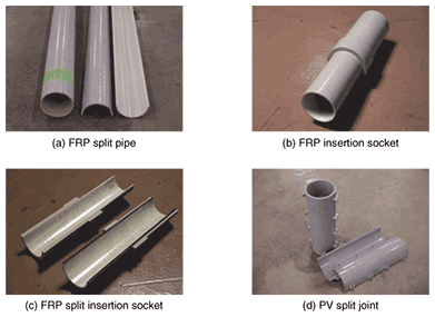
3.1 OverviewThe main constituents used in the repair of bridge-supported conduits are fiber reinforced plastic (FRP) split pipes, FRP insertion sockets, FRP split insertion sockets, and polyvinyl (PV) split joints (Fig. 4). The sockets are used in repairs at the sides of bridge abutments, where they are inserted into the conduit at the side of the bridge abutment after the corroded parts have been cut away. Solid insertion sockets are used for empty conduits while split insertion sockets are used for conduits that have cables running through them.
The FRP materials used in this repair technique primarily consist of unsaturated polyester resin and glass fiber, which combine to form a strong lightweight material that is far superior to other pipe materials. The principal pipe materials that have become standardized among NTT businesses are compared in Table 1, which lists their physical properties relative to hard PVC (polyvinyl chloride), which is a similar pipe material. Note that the linear expansion coefficient of FRP pipe is similar to that of steel pipes, so seasonal changes in temperature have hardly any effect. Furthermore, comparing FRP pipe with the stainless steel pipe used until now in the repair of bridge-supported conduits, we can see that its coefficients of elasticity and linear expansion are very similar but its weight is less than one third, so it should be lighter and easier to work with.
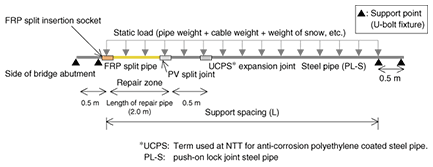
To prevent harmful gaps from occurring at the mating surfaces of the FRP split pipes, a standard twist ratio (the ratio of the twist angle to pipe length) is provided as a structural quality specification to ensure that uniform quality and precision are maintained. 3.2 PerformanceBridge-supported conduits are subjected to both static and dynamic loads. Static loads include the weight of the conduit itself, the weight of the cables inside it, and the weight of snow resting on top, while dynamic loads include vibrational loads caused by earthquakes and road traffic. It is essential that the conduit is of sufficient quality to withstand these loads after the repair has been made. It must have sufficient resistance to shearing and flattening of the parts themselves, and the repaired section must have sufficient strength to withstand bending to ensure the durability of the whole structure. Our investigations of static and dynamic loads are summarized below. (1) Static loads We conducted verification tests to determine whether a conduit repaired using our technique could retain a similar amount of twist to an existing bridge-supported conduit. This is a good criterion for evaluation under static loads. We determined the stresses acting on the conduit based on the physical properties and the loading forces described above. This was done using the experimental setup shown in Fig. 5. The length of the FRP split pipe was 2 m. We investigated the applicability of the technique to static loads that are constantly applied to a bridge-supported conduit by considering the loading patterns in three different regions of Japan—an ordinary region (snow depth ≤0.5 m) and two heavy snowfall regions (≤1 m and ≤2 m)—and with different combinations of supporting intervals.
As a result, the amount of bending and the permitted value of static loading in the vicinity of a repair were found to be within the applicable range for bridge-supported conduit in regions with ordinary snowfall conditions and at positions under bridges where snow does not settle and where the repair section is supported at intervals of no more than 2.5 m. (2) Dynamic loads During an earthquake, vibrations propagate to bridge-supported conduits through the bridges and supporting fixtures. To cope with longitudinal extension and contraction of the pipe materials, we used a structure where the expansion overlap is similar in size to existing expansion joints at a PV split joint and which can thus be expected to perform in a similar way in the longitudinal direction. Traffic vibration produces effects similar to those of an earthquake in that the bridge is vibrated by passing vehicles and this vibration propagates to the bridge-supported conduit via the supporting fixtures. We assumed that traffic vibration mainly causes the bridge-supported conduit materials to undergo repeated vibration in the vertical direction. We constructed the test setup shown in Fig. 6 and performed verification tests by generating simulated vertical vibration. The results of these tests confirmed that no abnormalities were caused by vibration fatigue.
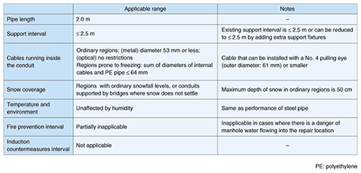
3.3 Operational constraintsThere are many different ways in which conduits can be attached to bridges, and the cables inside them are also often different. Since the internal diameter of the conduit is reduced by the insertion sockets used in repairs at bridge abutments, we checked the range of cases to which our technique is applicable in addition to checking the operational constraints (Table 2).
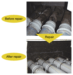
3.3.1. Constraints on cables that can be re-inserted due to reduction in diameterThe internal diameter of ordinary underground conduits is roughly 80 mm, but when insertion sockets are used, the internal diameter is limited to 67 mm. Therefore, taking into consideration factors such as the angular offset needed to attach the insertion sockets, we performed cable insertion tests in which the effective internal diameter (the space that can be reliably assured for the insertion and removal of cables) was set to 64 mm. These tests confirmed that the cables listed in Table 2 could be inserted and removed without damaging the insertion socket connections, cables, or repaired pipes. In line with this, for this repair work we chose to use quality assurance specifications specifying the use of a conduit inspection mandrel 64 mm in diameter and 450 mm long after split pipe repairs. 3.3.2. Finished shape and quality confirmationWe performed trial verification work at actual installations, and we checked the operational constraints of this work and the quality of the resulting repairs (Fig. 7). It was possible to perform repairs without difficulty even on conduits with cables already installed. As a quality check on the finished shape, we also inspected the repaired parts after six months. We visually checked for signs such as discoloration of the pipe materials and the opening of gaps at interconnecting parts, and we used offset measurements to measure the amount of movement in the repaired parts. These checks did not reveal any obvious defects and confirmed that there were no quality issues.
4. Future developmentThis repair technique is scheduled to be introduced by NTT East and West in fiscal year 2008. In the future, we will provide technical support for its introduction, and we will work at developing repair and reinforcement techniques aimed at an even wider range of applications, including confined locations. We are trying hard to contribute to NTT's business by promoting research and development related to techniques for the operation and maintenance of NTT infrastructure facilities. |
|||


