 |
|||||||||||||||||||
|
|
|||||||||||||||||||
|
Special Feature: Light Source Technologies for Sensing Applications Vol. 7, No. 1, pp. 23–28, Jan. 2009. https://doi.org/10.53829/ntr200901sf4 Mid-infrared Wavelength Conversion Laser for Highly Sensitive Gas DetectionAbstractThis article describes a compact sub-milliwatt mid-infrared laser source based on difference frequency generation in a quasi-phase-matched LiNbO3 waveguide directly pumped by two laser diodes. It operates in continuous wave mode at ambient temperatures, and we have obtained high outputs of up to 0.20 mW for a 3.4-µm laser source. It is applicable to highly sensitive detection of various atmospheric gases (e.g., CH4, CO, and CO2) and we have demonstrated realtime detection of methane gas absorption lines.
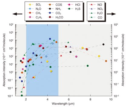
1. IntroductionLaser-based gas sensing is attractive because it can provide a way to achieve highly sensitive, realtime, in-situ detection of various gases. The key to its success is compact, reliable, and cost-effective laser light sources operating in the infrared (IR) region, where various gases exhibit a large number of strong absorption lines originating from fundamental and rovibrational (rotational and vibrational) absorption [1]. Currently, near-IR distributed feedback (DFB) laser diodes (LDs) developed for telecommunications are used for gas sensing because they satisfy all of the above requirements. However, there is a strong need to develop mid-IR laser sources because the absorption intensities of most gases are higher in the mid-IR than in the near-IR by a factor of 100—10,000, as shown in Fig. 1 [1]. The use of mid-IR lasers thus greatly increases the sensitivity of gas sensing and/or greatly reduces the optical path length and system size. Mid-IR laser sources based on difference frequency generation in quasi-phase-matched (QPM) LiNbO3 (LN) are promising for these applications because they can provide continuous wave (CW) mid-IR light in the wavelength range from 2–5 µm and operate at ambient temperatures. However, in spite of their excellent sensitivity, the low conversion efficiency of the conventional bulk QPM-LN devices developed to date has limited their use because large, expensive, high-power lasers must be used together with the QPM-LN devices to obtain a reasonable amount of mid-IR output. In this article, we describe a QPM-LN device with a high conversion efficiency that we made by using a waveguide structure. Using this device, we have successfully constructed a mid-IR light source. We describe the operating principle of this light source and the device fabrication method. We also describe a demonstration of gas detection using this light source.
2. Principle of wavelength conversionWavelength conversion using QPM-LN is based on second-order nonlinear optical effects such as difference frequency generation, second-harmonic generation, sum frequency generation, and optical parametric oscillation. Of these, we chose to use difference frequency generation to generate mid-infrared light. When two input lights, namely pump and signal lights with wavelengths of λ1 = 2πc/ω1 and λ2 = 2πc/ω2, respectively, are launched into a nonlinear crystal, difference-frequency light λ3 = 2π c/ω3 with a frequency of ω3 (= ω1 – ω2) is generated, where c is the velocity of light. This can be expressed using wavelength as
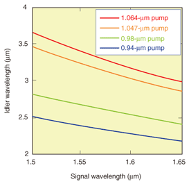
With mid-IR light generation, the difference frequency light is called the idler. The relationship between the idler and signal wavelengths at various pump wavelengths is shown in Fig. 2. Mid-IR light can be generated with a pump and signal combination chosen from commercially available near-IR telecommunications lasers. To achieve efficient wavelength conversion from the interaction of the above three waves, it is essential to satisfy the phase matching condition (Δk = 0) in which phase mismatch Δk is defined by
In this equation, n1, n2, and n3 are the refractive indices at the respective wavelengths λ1, λ2, and λ3. In most nonlinear crystals, this phase-matching condition can be satisfied only by a limited combination of wavelength and polarization. QPM alleviates the phase matching constraint and allows the wavelength conversion of arbitrary wavelength combinations in the wavelength region where the material is transparent. With the QPM technique, phase matching is achieved by fabricating a periodically poled structure whose spontaneous polarizations are reversed through 180° with period Λ with respect to the light propagation direction in nonlinear crystal. We can obtain various different wavelength conversions simply by designing different poling periods. The structure of a QPM-LN device is shown schematically in Fig. 3. Efficient wavelength conversion is achieved by satisfying the phase matching condition (Δk = 0), where the phase mismatch Δk is defined by
On the basis of a small signal approximation, where the attenuation of the two input lights powers P1 and P2 is negligible, the power of the converted light P3 with a device length L is given by Eq. (4), where η (%/Wcm2) represents the conversion efficiency per unit length and is given by Eq. (5).
The conversion efficiency η becomes constant (η = ηmax) when the phase matching condition is satisfied. Therefore, Eq. (4) means that the power of the converted light P3 improves in proportion to the input powers P1 and P2 and the square of the device length L.
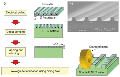
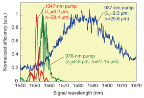
3. Device fabrication3.1 Direct bonding and waveguide fabricationThe conversion efficiency of QPM-LN is inversely proportional to the interaction cross-section. The waveguide structure is very effective for achieving efficient wavelength conversion because three interacting lights are confined in a small core area. We fabricated a waveguide by using the direct-bonding technique [2]. The fabrication process is summarized schematically in Fig. 4(a). We prepared 3-inch LN and LiTaO3 (LT) substrates for the waveguide layer and substrate, respectively. A periodically poled structure was formed in advance on the LN substrate. The two wafers were brought into contact in a clean atmosphere and then annealed at 500°C to achieve complete bonding at the atomic level. The waveguide layer thickness was reduced to around 10 µm by lapping and polishing. We then fabricated ridge waveguides by using a dicing saw. A microscope photograph of the fabricated ridge waveguides is shown in Fig. 4(b). A smooth flat sidewall surface was achieved by mechanical cutting with a fine diamond blade. We achieved a conversion efficiency of 40%/W for 3.2-µm generation [3]. This conversion efficiency is one hundred times higher than that obtained with bulk QPM-LN. Phase-matching curves for mid-IR generation at various wavelengths are shown in Fig. 5. This graph shows the dependence of the output on signal wavelength. Different output wavelengths can be obtained by choosing an appropriate pump wavelength and an appropriate periodic poling pitch Λ. We have also developed 2-µm-band QPM-LN waveguides and achieved high conversion efficiencies of 100 and 87%/W for 2.3- and 2.7-µm generation, respectively [4], [5].
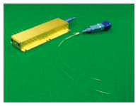
3.2 Module fabricationThe fabricated waveguide was housed in a module package. The fabricated wavelength conversion module [6] is shown in Fig. 6. To excite the transverse magnetic mode of the waveguide, we used a polarization-maintaining fiber pigtail designed for 980-nm light as an input fiber. A V-groove connection technique was used to splice the waveguide and the input fiber [7]. The module has a Peltier element and a thermistor to control the waveguide temperature. A Si filter is used as the output window of the module. This filter rejects the pump light but allows the signal light to pass. The signal light is useful for aligning the mid-IR output beam, which is difficult to see.
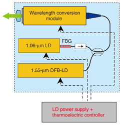
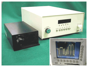
3.3 Structure of mid-IR laserThe structure of the mid-IR laser is shown schematically in Fig. 7. We fabricated a 3.4-µm laser for detecting methane (CH4) gas. We achieved a compact, reliable, cost-effective mid-IR laser without using either a fiber amplifier or a high-power solid-state laser. This laser consists of two LDs, a wavelength division multiplexing fiber coupler, and a QPM-LN module. The signal was obtained from a 1.55-µm band DFB-LD and pumped by a 1.064-µm FBG-stabilized single-mode LD (FBG: fiber Bragg grating), which was developed as a compact low-cost pump laser source [8].The two LDs and the wavelength conversion module were assembled with a polarization-maintaining fiber and then packaged in a box (90 × 180 × 50 mm3). The developed mid-IR laser source and driver are shown in Fig. 8. We obtained high CW output of 0.2 mW.
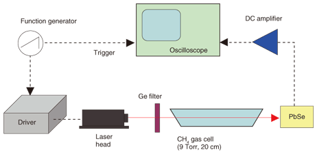
3.4 Demonstration of gas detectionThe experimental setup we used to demonstrate CH4 gas detection is shown in Fig. 9. The driver developed for use with the laser head is capable of modulating mid-IR light by modulating the current of the DFB-LD (signal). The signal wavelength was modulated by modulating the DFB-LD injection current with a triangular wave. The mid-IR output was collimated, passed through a CH4 gas cell (9 Torr, 20 cm), and detected with a PbSe detector. The dependence of the detected idler power on time was observed using an oscilloscope (inset of Fig. 8). The left side of the horizontal axis corresponds to the longer idler wavelength side. CH4 gas has strong absorption bands around 3.3 µm, and we successfully observed CH4 absorption lines.
4. ConclusionWe have developed wavelength conversion lasers using QPM-LN waveguides. These lasers use difference frequency generation in a highly efficient fiber-pigtailed QPM-LN waveguide module and two LDs. These components are fiber-coupled to each other, so they are robust and reliable. A fiber-pigtailed wavelength conversion module was fabricated by splicing a polarization-maintaining fiber to a direct-bonded QPM-LN ridge waveguide by using the V-groove connection technique. We obtained high output of up to 0.20 mW for the 3.4-µm laser source and demonstrated the measurement of CH4 absorption lines. The laser sources can cover wavelengths of up to about 5 µm, where LN is transparent. These compact sub-milliwatt mid-IR laser sources based on difference frequency generation are promising for use in high-sensitivity, realtime, and in-situ measuring systems for various gases. References
|
|||||||||||||||||||


