|
|||||||||||||||||||||
|
|
|||||||||||||||||||||
       |
Letters Vol. 8, No. 1, pp. 40–45, Jan. 2010. https://doi.org/10.53829/ntr201001le2 Earthquake-proofing Technologies for Conduits Attached to Seismically Isolated BridgesAbstractThis article describes technologies for preventing damage to telecommunication cables inside conduits attached to bridges. Although major bridges in Japan have recently been retrofitted to make them into seismically isolated structures as part of an earthquake-proofing program, existing telecommunication conduits attached to such bridges were not designed to cope with the large displacements produced by major earthquakes. We have examined the deformation capabilities required of such conduits and developed suitable technologies using commercially available materials. 
1. IntroductionSince the 1995 Kobe Earthquake, many road bridges in Japan have been reinforced (Table 1). The main seismic reinforcement method used for large bridges has been seismic isolation, which increases the vibration period and attenuates the vibration amplitude, thereby reducing the inertial force acting on upper structures. As a result, the relative displacement between superstructure and substructure has increased and superstructures move not only in the direction of the bridge”s axis (axial direction), but also in the direction perpendicular to it (perpendicular direction), as shown in Fig. 1. There are concerns that conduits attached to existing bridges, which were not designed to accommodate large displacements in two directions, will be damaged and that this could lead to cable damage and service disruptions. The type of damage suffered by a conduit attached to a seismically isolated bridge is schematically illustrated in Fig. 2.
The need to develop earthquake-proofing technologies became urgent after the severe damage that occurred to telecommunication conduits in the 2007 Chuetsu-oki Earthquake. We have defined the deformation capabilities required of bridge-attached conduits and examined ways to achieve them through an analysis of the seismic behavior of seismically isolated bridges. 2. Existing bridge-attached conduitsExisting facilities have expansion joints at places where relative displacement occurs, such as at abutments, as shown in Fig. 3. Even though the expansion and contraction specifications were designed to cope with thermal deformation and seismic movement, only one displacement direction (axial) was considered and the maximum displacement considered was only 10 cm, which is less than the displacement expected for a seismically isolated bridge. Therefore, there is concern that attached conduits and the cables inside them will be damaged by perpendicular displacement of the superstructure when the distance between the abutment and conduit support is short or when conduits pass through an aperture at the end of a bridge beam.
3. Analysis of seismic behavior of seismically isolated bridgeWe have examined the expected horizontal displacement of 26 bridges that have rubber supports where telecommunication conduits are attached. We found that seismically isolated bridges were designed to withstand a displacement of approximately 30 cm in the axial direction and also to move in the perpendicular direction. Among the bridges we examined, the maximum displacement design value was 60 cm. We also performed a dynamic analysis of the seismic behavior of the bridges using two different earthquake models for large-scale earthquakes occurring at a plate boundary and for inland earthquakes. The results showed that relative displacements of up to 60 cm in the axial direction and 40 cm in the perpendicular direction occur at abutments. Taking these values as targets, we examined countermeasures that could protect cables and ensure the continued availability of telecommunication services. 4. Seismic behavior of existing bridge-attached facilitiesWe experimentally verified the behavior of existing attached conduits when seismically isolated bridges were displaced by a large amount, corresponding to an earthquake. 4.1 Axial displacement testTo verify the deformation characteristics and behavior of conduits and expansion joints under large displacements up to failure, we performed static load tests (Fig. 4). The abutment side and the support fixture side were both set as fixed, and the displacement load was controlled by a hydraulic jack. An optical fiber was placed inside the conduit to measure the transmission loss after failure. The average frictional tension was loaded onto the optical fiber. As the displacement increased, the conduit (polyvinyl pipe) bent, and when the displacement reached 20 cm, a steel pipe pierced the polyvinyl pipe at the expansion joint and destroyed the joint. In some cases, the cable”s coating was damaged. Therefore, if relative displacements during an earthquake are expected to be more than 12 cm, the expansion and contraction lengths need to be increased.
4.2 Perpendicular displacement testWe also investigated the behavior of an attached conduit and expansion joint under perpendicular displacement through a static load test (Fig. 5). The transmission loss of the optical cable was also measured in this test. We found that a polyvinyl pipe bent by a large amount, so it could follow perpendicular displacement of a girder to some extent. The expansion joint, which was broken by the bending force, tended to be the weak point. Moreover, the sharply rising bending force and tension broke the optical fiber. The allowable displacement in the perpendicular direction is inversely proportion to the distance between the expansion joint and the first support fixture.
5. Countermeasures and earthquake-resistance evaluation testWe considered the composition of facilities that would be able to accommodate a large displacement in both the axial and perpendicular directions of a bridge and we also considered how such facilities could be constructed using commercially available materials. To prevent damage from our assumed displacements, we made a test rig consisting of corrugated FEP (fluorinated ethylene propylene) pipe and an expansion section able to accommodate a large degree of movement (Fig. 6). We also considered countermeasures based on the use of slit corrugated FEP pipe for existing attached conduits.
To verify the applicable area of the countermeasures, we performed repeated deformation tests using a single-axis shaking table. Axial and perpendicular displacements were applied incrementally in 10-cm steps until the conduit broke, and the transmission loss of the optical cable was also measured. In the axial uniaxial shaking test, the expansion section managed to absorb displacements of up to 60 cm in both the contraction and expansion directions and there was no damage to either the pipe or cables. The perpendicular uniaxial shaking test results showed that our countermeasures for preventing conduit and cable damage worked. The range in the perpendicular direction that our countermeasures can handle is shown in Fig. 7. According to previous research on seismically isolated bridges, the distance between joint and beam end aperture is usually more than 30 cm. Thus, we confirmed that these countermeasures can protect cables in the case of limited bending angles that currently cause transmission faults in almost all areas.
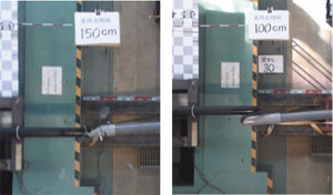
6. Performance evaluation test for actual earthquakesWe investigated the reliability of our countermeasures by using a biaxial shaking table and actual seismic records. On the basis of a dynamic analysis of seismically isolated bridges, we decided that the displacements to use in the shaking test should correspond to the seismic wave of an inland earthquake equivalent to the 1995 Kobe Earthquake, which was estimated to cause the largest beam displacement to date. The objectives of the test were to determine 1) how existing attached facilities are destroyed and how the breakage leads to transmission failure and 2) the behavior of countermeasures under actual earthquake conditions. Three specimens were made and tested for each case to determine the damage to the conduit and the transmission loss of the cable inside it. In the case of existing bridge-attached facilities, the expansion joint was withdrawn when the displacement reached 20 cm in the tensile direction regardless of the support distance. The exposed cable was whipped by repeated crushing of the two ends of the withdrawn conduits and finally fractured. The left photograph in Fig. 8 shows an example of a joint damaged by the crushing of a withdrawn conduit. The right photograph shows an example of a sharply bent and fractured cable resulting from a withdrawn conduit.
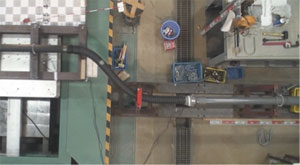
On the other hand, there was no damage to a conduit to which our countermeasures were applied or to the cable inside it, which demonstrates the effectiveness of our countermeasures for protecting telecommunication services from disruption even when bridges are severely shaken by an earthquake. A shaking test performed on a conduit with our countermeasures is shown in Fig. 9.
7. Future plansWe intend to investigate 1) the seismic performance of the countermeasures when multiple conduits are attached to a bridge, 2) behavior of a fireproof conduit, 3) long-term reliability, and 4) workability in trials before the countermeasures are deployed in a field (scheduled for 2009). References
|
||||||||||||||||||||